LiftMaster GH GH LOGIC VERSION 1 Manual - Page 7
Install Power Wiring & Control Station, Important Safety Notes, Control Station Wiring
 |
View all LiftMaster GH manuals
Add to My Manuals
Save this manual to your list of manuals |
Page 7 highlights
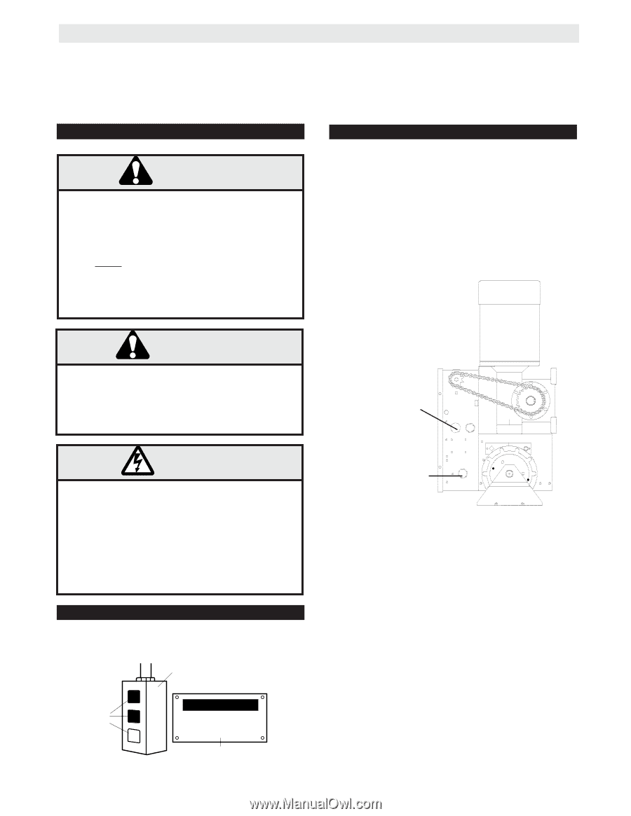
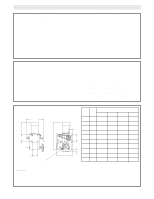
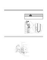
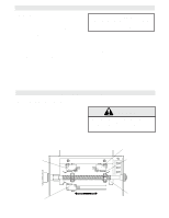
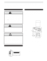
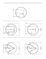
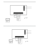
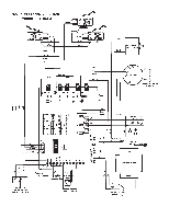
INSTALL POWER WIRING & CONTROL STATION Before installing control station be sure to follow all warnings described below. Failure to do so may result in severe injury to persons and/or damage to operator. Do not install any wiring or attempt to run the operator without consulting the wiring diagram. Install the optional Reversing Edge before proceeding with the Control Station installation. IMPORTANT SAFETY NOTES WARNING INSTALL THE CONTROL STATION WHERE THE DOOR IS VISIBLE, BUT AWAY FROM THE DOOR AND ITS HARDWARE. IF CONTROL STATION CANNOT BE INSTALLED WHERE DOOR IS VISIBLE, OR IF ANY DEVICE OTHER THAN THE CONTROL STATION IS USED TO ACTIVATE THE DOOR, A REVERSING EDGE MUST BE INSTALLED ON THE BOTTOM OF THE DOOR. FAILURE TO INSTALL A REVERSING EDGE UNDER THESE CIRCUMSTANCES MAY RESULT IN SERIOUS INJURY OR DEATH TO PERSONS TRAPPED BENEATH THE DOOR. CONTROL STATION WIRING Refer to Control Connection Diagrams on pages 11 & 14. Make connection through hole labeled for control. Do not run control wires in the same conduit as power wires. CABLE CONNECTION NOTE: Be sure to use the control box opening with the 7/8" dia. hole for CONTROL cable(s). All power wires use the 1-1/16" dia. hole. WARNING TO AVOID DAMAGE TO DOOR AND OPERATOR, MAKE ALL DOOR LOCKS INOPERATIVE. SECURE LOCK(S) IN "OPEN" POSITION. IF THE DOOR LOCK NEEDS TO REMAIN FUNCTIONAL, INSTALL AN INTERLOCK SWITCH. 1-1/16" dia. Power Wiring Access Hole WARNING DISCONNECT POWER AT THE FUSE BOX BEFORE PROCEEDING. OPERATOR MUST BE PROPERLY GROUNDED AND CONNECTED IN ACCORDANCE WITH LOCAL ELECTRICAL CODES. NOTE: THE OPERATOR SHOULD BE ON A SEPARATE FUSED LINE OF ADEQUATE CAPACITY. ALL ELECTRICAL CONNECTIONS MUST BE MADE BY A QUALIFIED INDIVIDUAL. MOUNT WARNING NOTICE IMPORTANT: Mount WARNING NOTICE beside or below the push button station. Control Station Push Buttons OPEN CLOSE STOP WARNING TO PREVENT ENTRAPMENT DO NOT START DOOR DOWNWARD UNLESS DOORWAY IS CLEAR WARNING Notice 7/8" dia. Control Wiring Access Hole (Opposite Side) 1. Complete electrical connections to the operator and the control station. Fasten the control station to the wall and MOUNT THE WARNING NOTICE BESIDE OR BELOW THE PUSH BUTTON STATION. 2. Apply power to the operator. Press OPEN push button and observe direction of door travel and then Press the STOP button. If door did not move in the correct direction, check for improper wiring at the control station or between operator and control station. If the operator is three phase and control station wiring is correct, exchange any two of the three incoming power leads. If electrical problems persist, call our Toll Free number for assistance (1-800-528-2806). 7
-
 1
1 -
 2
2 -
 3
3 -
 4
4 -
 5
5 -
 6
6 -
 7
7 -
 8
8 -
 9
9 -
 10
10 -
 11
11 -
 12
12 -
13
-
14
-
15
-
16
-
17
-
18
-
19
-
20
 |
 |