LiftMaster HCT HCT501130 Manual
LiftMaster HCT Manual
 |
View all LiftMaster HCT manuals
Add to My Manuals
Save this manual to your list of manuals |
LiftMaster HCT manual content summary:
- LiftMaster HCT | HCT501130 Manual - Page 1
- LiftMaster HCT | HCT501130 Manual - Page 2
- LiftMaster HCT | HCT501130 Manual - Page 3
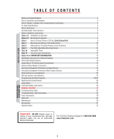
Programming the Radio Receiver Replacing the Control Board Audio Alarm Important Safety Instructions MANUAL RELEASE Troubleshooting Table Troubleshooting / LED Information Parts Illustrations Parts List Maintenance Accessories Operator Notes 2 3 3 4 5 5 6 7 8 9 10 11 12 12 13 14 15 15 16 17 18 - LiftMaster HCT | HCT501130 Manual - Page 4
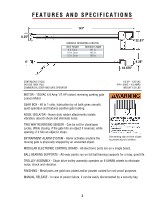
run on full ball bearing supports for a long, quiet life. TROLLEY ASSEMBLY - Chain drive trolley assembly operates on 6 UHMW wheels to eliminate noise, shock and vibration. FINISHING - Metal parts are gold-zinc plated and/or powder coated for rust-proof purposes. MANUAL RELEASE - In case of power - LiftMaster HCT | HCT501130 Manual - Page 5
including how to turn off power and how to operate the manual disconnect feature. • Leave safety instructions, product literature, installation manual and maintenance manual with end user. • Explain to the owners the importance of a service/maintenance contract that includes a routine re-testing of - LiftMaster HCT | HCT501130 Manual - Page 6
location or building such as a factory or loading dock area or other locations not intended to service the general public. Class IV - Restricted access vehicular gate operator A vehicular gate operator (or system) intended for use in a guarded industrial location or building such as an airport - LiftMaster HCT | HCT501130 Manual - Page 7
manual and safety instructions. • Routinely check of all operator functions and gate/door movement. • Discontinue use if safety systems operate . • Actively discourage pedestrian use of the vehicular operating system. • Prevent anyone from playing near any part of the system. • Never allow anyone to - LiftMaster HCT | HCT501130 Manual - Page 8
SAFETY INSTALLATION INSTRUCTIONS 1) Vehicular gate systems provide convenience and security. Gate systems are comprised of many component parts. The gate operator is only one component. Each gate system is specifically designed for an individual application. 2) Gate operating system designers, - LiftMaster HCT | HCT501130 Manual - Page 9
INSTALLATION OF OPERATOR Make sure the gate/door opens and closes smoothly. Gate/door should stay in the open position when springs are properly balanced. STEP 1 With the - LiftMaster HCT | HCT501130 Manual - Page 10
CL Header Bracket CL Header Bracket CL CL STEP 4 Lift the operator and align with center mark on ceiling. Have someone hold the operator in place or use something as a support post, and bolt to ceiling. (A support post is not part of the operator. Use only for installation.) Concrete CL Anchor - LiftMaster HCT | HCT501130 Manual - Page 11
box BEFORE • ALL power wiring should be on a dedicated proceeding. Operator MUST be properly circuit and well protected. The location of the HCT Earth Ground Wire Black = 120 Vac Wire White = Neutral Wire Green = Earth Ground Wire Use UL Listed conduit to enclose power wires Chamberlain - LiftMaster HCT | HCT501130 Manual - Page 12
to be reset upon the event of a double entrapment alarm. When such an event occurs the alarm will continuously sound and the operator will not have any functionality until the board is reset. WARNING To prevent possible SERIOUS INJURY or DEATH from electrocution, disconnect electric power to - LiftMaster HCT | HCT501130 Manual - Page 13
STEP 8 Before Adjusting, Do the Following: 1. Disconnect power to the operator. 2. Push the limit nut lock plate inward. Roll the nut to the direction desired. 3. Place the plate back in the notch. 4. Reapply power to operator. 5. If further adjustment is needed, repeat the process. Push Plate - LiftMaster HCT | HCT501130 Manual - Page 14
2-WAY ADJUSTABLE REVERSING SENSOR STEP 9 Adjusted by Qualified Service Personnel REVERSE SENSOR CENTER SAFETY EXIT 3 1 3 Maximum Sensitivity SENSOR ALARM W4 GBA MS from 1 to 60 seconds (Timer ON), For push open/push close type operation (Timer OFF). OPEN LEFT OPEN RIGHT Timer OFF 12 - LiftMaster HCT | HCT501130 Manual - Page 15
Volts DC Master/Second Link: Not used in normal installation Wire 13 + Radio Power 12 Relay 11 - 24 Volt WARNING: To ENSURE proper operation of safety devices: • ENSURE bare wire makes good contact inside removable terminal connectors. • DO NOT let wire insulation interfere with connection. 13 - LiftMaster HCT | HCT501130 Manual - Page 16
IMPORTANT INFORMATION STEP 12 MER 60 CENTER SAFETY EXIT OFF 1 3 ON OPEN LEFT OPEN RIGHT SENSOR ALARM W4 GBA MS LINK CENTER SAFETY EXIT ALARM SENSOR DC-BACKUP SYSTEM ON SENSORS 1 3 1 3 REVERSE SENSOR TIMER 60 3 OFF OPEN LEFT 1 3 ON OPEN RIGHT COMMAND PROCESSED FIRE DEPT. - LiftMaster HCT | HCT501130 Manual - Page 17
INSTRUCTIONS FOR OPTIONAL SYSTEMS CENTER SAFETY EXIT QCC AB OPEN STOP SAFETY EXIT N.O. Gnd N.C. Gnd N.O. Gnd Com N.C. N.O. Com N.O. N.C. Gnd Gnd B A QCC is designed for slide gate operators only! Omni Option Board 1 & 2 - Open Command see Accessories page 3 & 4 - Stop Command 10 & 11 - - LiftMaster HCT | HCT501130 Manual - Page 18
ALARM/PROXIMITY SWITCH CONNECTIONS Omni "Option Board" needed to perform this function. See Accessories page. QCC AB OPEN STOP CLOSE MAGLOCK ALARM ARMED M/S LINK Alarm 10 - Common 11 - Normally Open Armed 12 - Normally Closed 13 - Ground 10 11 12 13 Omni Option Board Proximity Switch see - LiftMaster HCT | HCT501130 Manual - Page 19
OPTIONAL RELAY ADAPTER CONNECTION See Accessories page for Relay Adapter Module CENTER SAFETY EXIT SENSOR ALARM W4 GBA MS LINK CENTER SAFETY EXIT ALARM SENSOR DC-BACKUP SYSTEM ON SENSORS 1 3 1 3 REVERSE SENSOR TIMER 60 3 OFF OPEN LEFT 1 3 ON OPEN RIGHT COMMAND PROCESSED FIRE - LiftMaster HCT | HCT501130 Manual - Page 20
Entrapment Protection (Contact Sensor) Edge Sensor Wiring When touched, the electrically activated edge sensors immediately signal the door/gate operator to stop and reverse. Property owners are obligated to test edges regularly. ®OmniControl Surge Suppressor P/N Q410 Patent Pending 123456 - LiftMaster HCT | HCT501130 Manual - Page 21
Strike Open Push Button Radio Receiver ® OmniControl Surge Suppressor P/N Q410 Patent Pending (LiftMaster Commercial Protector System shown) 3 4 GBA M/S Link Center Loop Safety Loop in class I or class II gate operator. See Accessories page for acceptable non-contact safety devices. 19 - LiftMaster HCT | HCT501130 Manual - Page 22
Off Conference Rm 2, 3 Off On On Main Room Conference Room 1 Conference Room 2 Comp. Serve 2 Air (2) Conditioner Comp. Serve 1 Off Off Gate Operator Eug. Rm Oper. Rm Eug. Dept. Manu. 1 Rm Main Dept. Manu. 2 Rm CENTER SAFETY EXIT Twisted wires must be 6 turns per foot "Minimum" Wire-Loop - LiftMaster HCT | HCT501130 Manual - Page 23
the same dimensions. • Have the same number of wire turns. Common 6 Normally Open 5 External 115 Vac "Exit" Loop Detector - Allows operator to automatically open for exiting vehicles. OUT SaLfeotoyp SaLfoeotyp ELxoitop IN OUT SaLfeotoyp SaLfoeotyp Note: External 115 Vac Loop Detectors - LiftMaster HCT | HCT501130 Manual - Page 24
are prohibited, except for changing the code setting or replacing the battery. THERE ARE NO OTHER USER SERVICEABLE PARTS. Tested to Comply with FCC Standards for home or office use. Operation is subject to the following two conditions: (1) this device may not cause harmful interference, and (2) this - LiftMaster HCT | HCT501130 Manual - Page 25
Within 30 seconds, press and hold the button C P2 on the hand-held remote that you wish to M operate your operator. Power 24V 12V The opener will now operate when the push Supply button on either the receiver or the remote Jumper Output Duration Terminals Security Mode control is pressed - LiftMaster HCT | HCT501130 Manual - Page 26
. Unscrew 3 nuts and remove board. WARNING To prevent possible SERIOUS INJURY or DEATH from electrocution, disconnect electric power to operator BEFORE installing. ALL electrical connections MUST be made by a qualified individual. ® OmniControl Surge Suppressor P/N Q410 Patent Pending GBA - LiftMaster HCT | HCT501130 Manual - Page 27
SERIOUS INJURY or DEATH: 1) READ AND FOLLOW ALL INSTRUCTIONS. 2) NEVER let children operate or play with gate or door controls. Keep the maintained. Read the manual. An improperly operating or balance gate or door could cause SERIOUS INJURY or DEATH. Have a qualified service technician make repairs - LiftMaster HCT | HCT501130 Manual - Page 28
RELEASE WARNING: To reduce the risk of SERIOUS INJURY or DEATH from a falling gate/door: • If possible, use manual release to disengage trolley ONLY when door is CLOSED. Weak or broken springs or unbalanced gate/door could result in an open gate/door falling - LiftMaster HCT | HCT501130 Manual - Page 29
TROUBLESHOOTING a normal response of the gate/door operator. It does not represent necessarily that there is a problem. Check inputs for command. Timer LED frequency. 4. The loop detector is too sensitive. For Toll Free Technical Support: 1-800-528-2806 1. Reset the loop detector (If you use Plug - LiftMaster HCT | HCT501130 Manual - Page 30
TROUBLESHOOTING LED INFORMATION Resetting Motor CENTER SAFETY EXIT Press firmly to reset thermal breaker on the motor. SENSOR ALARM CENTER SAFETY W4 GBA MS LINK ALARM - LiftMaster HCT | HCT501130 Manual - Page 31
PARTS ILLUSTRATIONS Q404 Q067 Q620 Q068 312HM Q250 Q018 Q248 Q071 Q027 Q070 Q097 Q081 Q092 Q074 Q075 Q082 Q410 Q029 Q400DHCT Q073 Q072 Q006 Q076 - LiftMaster HCT | HCT501130 Manual - Page 32
PARTS LIST 312HM - Single Channel Radio Receiver 1941240D - Chain #41 (per 10' box) Q006 - Button 40-3505 - U.L. Warning Sign (not shown) MAINTENANCE 1. Make sure the gate/door operates smoothly without the operator. 2. Make sure the gate/door track runs smoothly. 3. For chain maintenance, you can - LiftMaster HCT | HCT501130 Manual - Page 33
ACCESSORIES OMNIEXB Omni Option Board AELD Plug-In Loop Detector Q400MAU Omni Relay Adapter Module 377LM Wireless Keyless Entry 370LM 371LM 372LM 373LM 374LM CPTK33PH 3-Button Mini Remote 1-Button Remote 2-Button Remote 3-Button Remote 4-Button Remote Passport 3-Button Remote with HID - LiftMaster HCT | HCT501130 Manual - Page 34
OPERATOR NOTES 32 - LiftMaster HCT | HCT501130 Manual - Page 35
- LiftMaster HCT | HCT501130 Manual - Page 36
01-32393D ©2007, The Chamberlain Group, Inc. All Rights Reserved
-
 1
1 -
 2
2 -
 3
3 -
 4
4 -
 5
5 -
 6
6 -
 7
7 -
8
-
9
-
10
-
11
-
12
-
13
-
14
-
15
-
16
-
17
-
18
-
19
-
20
-
21
-
22
-
23
-
24
-
25
-
26
-
27
-
28
-
29
-
30
-
31
-
32
-
33
-
34
-
35
-
36
 |
 |