LiftMaster HCT HCT501130 Manual - Page 12
Mounting And Wiring Of Reset Switch, Warning
 |
View all LiftMaster HCT manuals
Add to My Manuals
Save this manual to your list of manuals |
Page 12 highlights
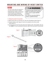
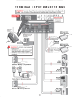
MOUNTING AND WIRING OF RESET SWITCH STEP 7 The reset switch allows the operator to be reset upon the event of a double entrapment alarm. When such an event occurs the alarm will continuously sound and the operator will not have any functionality until the board is reset. WARNING To prevent possible SERIOUS INJURY or DEATH from electrocution, disconnect electric power to operator BEFORE installing. ALL electrical connections MUST be made by a qualified individual. 1. Disconnect power to the operator. 2. Mount reset switch at a minimum of 6' away from the gate/door jambs (Figure 1). 3. Plug the interface cable (Figure 2) into the J5 receptacle on the Omni control board (Figure 3). 4. Connect like wires from the reset switch to the interface cable. Twist together with wire nuts. NOTE: The wire connecting the interface cable to the reset switch is not provided. Figure 1 Figure 2 6' min. RESET RESET CENTER SAFETY EXIT Figure 3 SENSOR ALARM W4 OPEN QCC A GBA STMOSP LINKCLOSE B MAGLOCK ALARM ARMED M/S LINK ALARM SENSOR DC-BACKUP SYSTEM ON SENSORS 1 3 1 3 REVERSE SENSOR TIMER 60 3 OFF OPEN LEFT 1 3 ON OPEN RIGHT POWER OVERLOAD MADE IN USA Plug Reset Switch Connector to J5 Connector CLOSE STOP OPEN COMMAND PROCESSED FIRE DEPT. STRIKE OPEN RADIO RECEIVER GATE LOCKED EXIT LOOP SAFETY LOOP CENTER LOOP RESET MOTOR J5 DC-BACKUP CENTER SAFETY EXIT 10
-
 1
1 -
2
-
3
-
4
-
5
-
6
-
 7
7 -
 8
8 -
 9
9 -
 10
10 -
 11
11 -
 12
12 -
 13
13 -
 14
14 -
 15
15 -
 16
16 -
 17
17 -
18
-
19
-
20
-
21
-
22
-
23
-
24
-
25
-
26
-
27
-
28
-
29
-
30
-
31
-
32
-
33
-
34
-
35
-
36
 |
 |
