LiftMaster HCT HCT501130 Manual - Page 15
Terminal Input Connections, Step 11
 |
View all LiftMaster HCT manuals
Add to My Manuals
Save this manual to your list of manuals |
Page 15 highlights
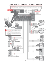
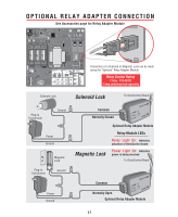
SENSOR ALARM DC-BACKUP T E R M I N A L I N P U T C O N N E C T I O N S W4 GBA MS LINK SYSTEM ON SENSORS TIMER 60 3 POWER OVERLOAD REVERSE SENSOR Important: Terminals 11 and 12 are the only terminals thaOtFFwill bOoNth1 Op3 en and/or Close with ALARM SENSOR a single push of a button. All other terminals1 wi3ll on1 ly o3 pen with a single push of a button. MADE IN USA OPEN LEFT OPEN RIGHT CLOSE STOP OPEN CENTER SAFETY EXIT STEP 11 COMMAND PROCESSED FIRE DEPT. STRIKE OPEN RADIO RECEIVER GATE LOCKED Output Power EXIT LOOP SAFETY LOOP CENTER LOOP RESET MOTOR Ground (-) 24 Vdc (+) ®OmniControl Surge Suppressor P/N Q410 Patent Pending 123456 7 8 9 10 11 12 13 Removable Terminal Connectors G BA M/S Link Center Loop Safety Loop - Exit Fire Dept. Strike Open Loop Key Switch Push Button + Radio Receiver Class 2 Supply 24 Volts DC Master/Second Link: Not used in normal installation Wire 13 + Radio Power 12 Relay 11 - 24 Volt WARNING: To ENSURE proper operation of safety devices: • ENSURE bare wire makes good contact inside removable terminal connectors. • DO NOT let wire insulation interfere with connection. 13 + Red 24 Volt 12 Grey 11 - Black 11 - Grey 3 Wire 24 Vdc Radio Receiver 4 Wire 24 Vdc Radio Receiver 3 4 External "Safety" Loop Detector Card Reader 10 9 ® ® 11 Ground (-) 13 24VDC (+) ® +24V COMMON SENSING EDGE INPUT INFRARED BLACK or BROWN INFRARED WHITE or BLUE 3 4 Photo Electric Sensors (Safety) 5 6 External "Exit" Loop Detector 13 Push Button 10 9 Phone Entry 10 12 3 9 456 789 HELP 0 Fire or Any Key Switch 8 7
-
 1
1 -
2
-
3
-
4
-
5
-
6
-
7
-
8
-
9
-
 10
10 -
 11
11 -
 12
12 -
 13
13 -
 14
14 -
 15
15 -
 16
16 -
 17
17 -
 18
18 -
 19
19 -
 20
20 -
21
-
22
-
23
-
24
-
25
-
26
-
27
-
28
-
29
-
30
-
31
-
32
-
33
-
34
-
35
-
36
 |
 |
