LiftMaster PPWR PPWR Passport Wiegand Reciever Manual
LiftMaster PPWR Manual
 |
View all LiftMaster PPWR manuals
Add to My Manuals
Save this manual to your list of manuals |
LiftMaster PPWR manual content summary:
- LiftMaster PPWR | PPWR Passport Wiegand Reciever Manual - Page 1
connections (Figure 2). Refer to your access system host owner's manual for more specific information. 5. Reconnect the keypad connector to the watertight connector to secure and seal the wiring. PASSPORT WIEGAND RECEIVER MODEL PPWR To prevent possible SERIOUS INJURY or DEATH from electrocution - LiftMaster PPWR | PPWR Passport Wiegand Reciever Manual - Page 2
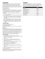
a facility code from any remote control in a batch that the PPWR will respond to. Also used to resolve any conflicts in code installed. Restores a memory backup from a memory module. An indicator appears on the LiftMaster® logo screen if a backup memory module is installed. NOTE: Content of memory - LiftMaster PPWR | PPWR Passport Wiegand Reciever Manual - Page 3
The PPWR receiver has the ability to learn a combination of remote control transmitters. See page 4 for a complete list of compatible accessories. Audible and visual warnings occur when the receiver capacity is exceeded. After 30 seconds of inactivity, the receiver times out and the LiftMaster® logo - LiftMaster PPWR | PPWR Passport Wiegand Reciever Manual - Page 4
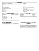
for a period of 1 year from the date of purchase. FOR TECHNICAL SUPPORT DIAL OUR TOLL FREE NUMBER: 1-800-528-2806 NOTICE: To comply with FCC . adjustment or modifications of this receiver are prohibited. THERE ARE NO USER SERVICEABLE PARTS. This device complies with Part 15 of the FCC rules and IC - LiftMaster PPWR | PPWR Passport Wiegand Reciever Manual - Page 5
Le PPWR est compatible avec les télécommandes Security✚ 2.0™ Passport et Passport Lite et barrières résidentielles est INTERDITE. 2. Installez le support de fixation sur la surface désirée au branchements (Figure 2). Consultez le manuel d'instructions pour de plus amples renseignements. 5. - LiftMaster PPWR | PPWR Passport Wiegand Reciever Manual - Page 6
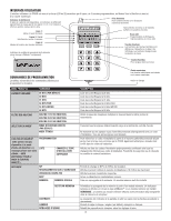
INTERFACE UTILISATEUR L'interface utilisateur du PPWR est muni d'un écran LCD de 22 caractères par des touches fonctions. Indicateur de module de sauvegarde de la mémoire (écran du logo LiftMaster® uniquement). Touches fonctions Les fonctions des touches fonctions sont définies par l'étiquette sur - LiftMaster PPWR | PPWR Passport Wiegand Reciever Manual - Page 7
cepteur PPWR est capable de reconnaître une série d'émetteurs télécommandés. Consultez la page 4 pour obtenir une liste complète des accessoires compatibles. Des avertissements visuels et sonores sont donnés lorsque le récepteur dépasse sa capacité. Après 30 secondes d'inactivité, le logo LiftMaster - LiftMaster PPWR | PPWR Passport Wiegand Reciever Manual - Page 8
de 15 pi 86LM Rallonge de 25 pi 86LMT Transformateur : 24 V c. a 95LM PIÈCES DE REMPLACEMENT Antenne droite K76-36681 Module mémoire K1D7530-3 Support de fixation K13-36651-2 POUR L'ASSISTANCE TECHNIQUE, APPELER LE NUMÉRO SANS FRAIS SUIVANT : 1-800-528-2806 GARANTIE LIMITÉE D'UN AN La soci
-
 1
1 -
 2
2 -
 3
3 -
 4
4 -
 5
5 -
 6
6 -
 7
7 -
8
 |
 |
1
To prevent possible SERIOUS INJURY or DEATH from electrocution:
•
Be sure power is NOT connected BEFORE installing the receiver.
To prevent possible SERIOUS INJURY or DEATH from a moving gate
or garage door:
•
ALWAYS keep remote controls out of reach of children. NEVER
permit children to operate, or play with remote control transmitters.
•
Activate gate or door ONLY when it can be seen clearly, is properly
adjusted, and there are no obstructions to door travel.
•
ALWAYS keep gate or garage door in sight until completely closed.
NEVER permit anyone to cross path of moving gate or door.
To prevent possible SERIOUS INJURY or DEATH, the use of
CONSTANT OPERATION on residential openers is PROHIBITED.
When a receiver is used to activate a commercial door opener, a
reversing edge MUST be installed on the bottom of the door. Failure to
install a reversing edge under these circumstances may result in
SERIOUS INJURY or DEATH to persons trapped beneath the door.
PASSPORT WIEGAND RECEIVER
MODEL PPWR
APPLICATION
The PPWR is a Wiegand compatible output radio receiver utilizing
Security
✚
2.0™ technology. The PPWR is compatible with access system
host controllers utilizing 26 Bit, 30 Bit, 31 Bit 34 Bit (even or odd), and
50 Bit Wiegand code formats. The receiver has two modes of operation:
•
Pass Through Mode
- passes all received remote control signals to
the access system host controller.
•
Advanced Mode
- provides an additional layer of security in areas
where other remote controls may be operating. The receiver only
passes signals from a remote control with a previously programmed
facility code. All other signals are blocked.
The PPWR may be used with Security
✚
2.0™ Passport and Passport Lite
remote controls. This receiver is compatible with HomeLink
®
. For
programming or compatibility information visit www.homelink.com. The
receiver is watertight according to IP44 specification.
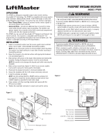
INSTALLATION
1.
Select a convenient location near the access system host controller
within “line of sight” of the intended transmitting location.
NOTE:
Do not mount the receiver in direct sunlight. Avoid mounting
the receiver in a metal enclosure or near other wireless receiving or
transmitting devices.
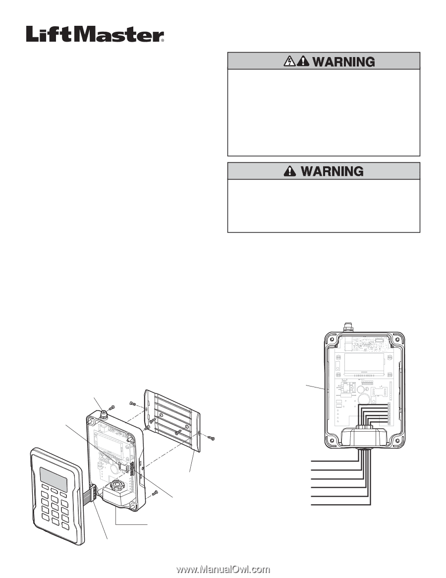
2.
Mount the bracket to the desired surface with appropriate hardware
(not provided)(Figure 1).
3.
Remove the 4 #8 screws on the back of the receiver and remove the
faceplate. Unplug the keypad connector from the control board.
NOTE:
Be careful not to damage the keypad cable while removing the
faceplate.
4.
Make wiring connections (Figure 2). Refer to your access system
host owner’s manual for more specific information.
5.
Reconnect the keypad connector to the board (labeled J9).
6.
Secure the faceplate with the 4 #8 screws previously removed.
7. Install the antenna (provided).
NOTE:
Use the optional 86LM or 86LMT antenna extension kit
(see page 4) to mount the remote antenna as high and far from
metallic objects as possible for best radio range.
8.
Snap receiver onto the mounting bracket and secure with the
#8 screws provided.
9.
Tighten the watertight connector to secure and seal the wiring.
Figure 1
Mounting Bracket
Antenna
Connector
Backup Memory
Module
Figure 2
Data 1 (to host)
Data 0 (to host)
12-24 VDC (+ Power Input)
- Power Input
Shield (to ground)
LED (from host)
Watertight Connector
J9
Keypad Connector
Receiver Without
Faceplate