Lowrance Elite-12 Ti178 US Inland No Transducer Elite Ti2 Installation Manual
Lowrance Elite-12 Ti178 US Inland No Transducer Manual
 |
View all Lowrance Elite-12 Ti178 US Inland No Transducer manuals
Add to My Manuals
Save this manual to your list of manuals |
Lowrance Elite-12 Ti178 US Inland No Transducer manual content summary:
- Lowrance Elite-12 Ti178 US Inland No Transducer | Elite Ti2 Installation Manual - Page 1
ELITE Ti2 Installation Manual ENGLISH www.lowrance.com - Lowrance Elite-12 Ti178 US Inland No Transducer | Elite Ti2 Installation Manual - Page 2
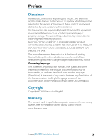
- Lowrance Elite-12 Ti178 US Inland No Transducer | Elite Ti2 Installation Manual - Page 3
subsidiaries, branches and affiliates reserve the right to make changes to specifications without notice. Governing language This statement, any instruction manuals, user guides and other information relating to the product (Documentation) may be translated to, or has been translated from, another - Lowrance Elite-12 Ti178 US Inland No Transducer | Elite Ti2 Installation Manual - Page 4
device may not cause harmful interference, and (2) this device must accept any interference received, including interference that may cause undesired operation 4 Preface | ELITE Ti² Installation Manual - Lowrance Elite-12 Ti178 US Inland No Transducer | Elite Ti2 Installation Manual - Page 5
can radiate radio frequency energy and, if not installed and used in accordance with the instructions, may cause harmful interference to radio communications. However, there is no guarantee that the than that necessary for successful communication. Preface | ELITE Ti² Installation Manual 5 - Lowrance Elite-12 Ti178 US Inland No Transducer | Elite Ti2 Installation Manual - Page 6
or a pay-per-MB type internet connection may require large data usage. Your service provider may charge you based on the amount of data you transfer. If you are unsure, contact your or both. SmartCraft VesselView® is a registered trademark of Mercury. 6 Preface | ELITE Ti² Installation Manual - Lowrance Elite-12 Ti178 US Inland No Transducer | Elite Ti2 Installation Manual - Page 7
Suzuki® is a registered trademark of Suzuki. About this manual This manual is a reference guide for installing units. Some features may not be activated or available for screenshots in the manual. As a result, screenshots of menus and dialogs may not match the look of your unit. Important text that - Lowrance Elite-12 Ti178 US Inland No Transducer | Elite Ti2 Installation Manual - Page 8
8 Preface | ELITE Ti² Installation Manual - Lowrance Elite-12 Ti178 US Inland No Transducer | Elite Ti2 Installation Manual - Page 9
settings 28 Alarms 29 Sonar settings 33 Autopilot settings 33 Fuel settings 36 Wireless settings 37 Network settings 41 3rd party support 41 SmartCraft VesselView integration 41 Suzuki engine integration 41 Yamaha engine integration 42 Evinrude engine integration Contents | ELITE Ti² Installation - Lowrance Elite-12 Ti178 US Inland No Transducer | Elite Ti2 Installation Manual - Page 10
42 Power-Pole anchors 43 Accessories 44 Supported data 44 NMEA 2000 compliant PGN List 49 NMEA 0183 supported sentences 51 Technical specifications 51 Elite Ti² 53 Dimensional drawings 53 ELITE 7Ti² 53 ELITE 9Ti² 54 ELITE 12Ti² 10 Contents | ELITE Ti² Installation Manual - Lowrance Elite-12 Ti178 US Inland No Transducer | Elite Ti2 Installation Manual - Page 11
cover D Power cable kit E 7-pin to 9-pin transducer adapter cable (Included with units that do not ship with a transducer) F Documentation pack Introduction | ELITE Ti² Installation Manual 11 - Lowrance Elite-12 Ti178 US Inland No Transducer | Elite Ti2 Installation Manual - Page 12
unit OFF • When ON press once to display the System Controls dialog, repeat short presses to cycle the backlight brightness 12 Introduction | ELITE Ti² Installation Manual - Lowrance Elite-12 Ti178 US Inland No Transducer | Elite Ti2 Installation Manual - Page 13
. The protective door should always be securely shut immediately after inserting or removing a card, in order to prevent possible water ingress. Introduction | ELITE Ti² Installation Manual 13 - Lowrance Elite-12 Ti178 US Inland No Transducer | Elite Ti2 Installation Manual - Page 14
Connectors ELITE Ti² AB C A Power and NMEA 0183 The NMEA 0183 functionality requires a combined Power and NMEA 0183 cable (sold separately) B NMEA 2000 C Sonar 14 Introduction | ELITE Ti² Installation Manual - Lowrance Elite-12 Ti178 US Inland No Transducer | Elite Ti2 Installation Manual - Page 15
be required to fit forced cooling. Warning: Inadequate ventilation and subsequent overheating of the unit may cause unreliable operation and reduced service life. Exposing the unit to conditions that exceeds the specifications could invalidate your warranty. Refer to the technical specifications in - Lowrance Elite-12 Ti178 US Inland No Transducer | Elite Ti2 Installation Manual - Page 16
. Removing the unit from the bracket Pull and hold the release handle and then pull the unit from the bracket. 16 Installation | ELITE Ti² Installation Manual - Lowrance Elite-12 Ti178 US Inland No Transducer | Elite Ti2 Installation Manual - Page 17
to the mounting surface material. 3. Screw down the bracket. 4. Mount the unit to the bracket using the knobs. Hand tighten only. Installation | ELITE Ti² Installation Manual 17 - Lowrance Elite-12 Ti178 US Inland No Transducer | Elite Ti2 Installation Manual - Page 18
Panel mounting Refer to the separate mounting template for panel mounting instructions. Removing the corner clips 18 Installation | ELITE Ti² Installation Manual - Lowrance Elite-12 Ti178 US Inland No Transducer | Elite Ti2 Installation Manual - Page 19
they interfere with mechanical systems • Run cables over sharp edges or burrs Do: • Make drip and service loops • Use cable-tie on all cables to keep them secure • Solder/crimp and insulate all wiring or a circuit breaker (closest available to fuse rating). Wiring | ELITE Ti² Installation Manual 19 - Lowrance Elite-12 Ti178 US Inland No Transducer | Elite Ti2 Installation Manual - Page 20
to be powered by 12 V DC. It is protected against reverse polarity, under voltage and over voltage (for a limited duration). 20 Wiring | ELITE Ti² Installation Manual - Lowrance Elite-12 Ti178 US Inland No Transducer | Elite Ti2 Installation Manual - Page 21
connected to up to three listener (receiver) devices, dependent on the hardware capabilities of the receiver. Power connection (included cable) AB C Wiring | ELITE Ti² Installation Manual 21 - Lowrance Elite-12 Ti178 US Inland No Transducer | Elite Ti2 Installation Manual - Page 22
D Not used E Talker A (Tx_A) F Talker B (Tx_B) G Listener A (Rx_A) H Listener B (Rx_B) I Ground (shield) Color Red Black -Yellow Yellow Blue Orange Green -- 22 Wiring | ELITE Ti² Installation Manual - Lowrance Elite-12 Ti178 US Inland No Transducer | Elite Ti2 Installation Manual - Page 23
Sonar Supports: • Sonar / CHIRP Sonar • DownScan • SideScan • Active Imaging/Active Imaging 3-in-1/TotalScan/StructureScan Ú Note: A 7-pin transducer socket (male) Pin Purpose 1 Shield 2 NET-S (+12 V DC) 3 NET-C (DC negative) 4 NET-H 5 NET-L Wiring | ELITE Ti² Installation Manual 23 - Lowrance Elite-12 Ti178 US Inland No Transducer | Elite Ti2 Installation Manual - Page 24
draw on each side of the power node is equal. Ú Note: 1 LEN (Load Equivalency Number) equals 50 mA current draw. 24 Wiring | ELITE Ti² Installation Manual - Lowrance Elite-12 Ti178 US Inland No Transducer | Elite Ti2 Installation Manual - Page 25
Ú Note: Do not connect the NMEA 2000 power cable to the same terminals as the engine start batteries, autopilot computer, bow thruster or other high current devices. Wiring | ELITE Ti² Installation Manual 25 - Lowrance Elite-12 Ti178 US Inland No Transducer | Elite Ti2 Installation Manual - Page 26
Controls dialog. If the Power key is released before the shut-down is completed, the power off process is cancelled. Software setup | ELITE Ti² Installation Manual - Lowrance Elite-12 Ti178 US Inland No Transducer | Elite Ti2 Installation Manual - Page 27
pressing the waypoint key during power on until the calibration utility screen comes up 4. Follow the instructions on the screen to perform the calibration. When completed, the unit returns to the application screen physical attributes of the boat. Software setup | ELITE Ti² Installation Manual 27 - Lowrance Elite-12 Ti178 US Inland No Transducer | Elite Ti2 Installation Manual - Page 28
alarm options in the system, with current settings. From this list you can activate, deactivate and change alarm limits. 28 Software setup | ELITE Ti² Installation Manual - Lowrance Elite-12 Ti178 US Inland No Transducer | Elite Ti2 Installation Manual - Page 29
transducers measure water depth from the transducer to the bottom. As a result, water depth readings do not account for the Software setup | ELITE Ti² Installation Manual 29 - Lowrance Elite-12 Ti178 US Inland No Transducer | Elite Ti2 Installation Manual - Page 30
temperature data is shared on the NMEA 2000 network. Installation Use this dialog to setup and configure available sources. 30 Software setup | ELITE Ti² Installation Manual - Lowrance Elite-12 Ti178 US Inland No Transducer | Elite Ti2 Installation Manual - Page 31
the transducer to the lowest point of the boat in the water or from the transducer to the water surface. Software setup | ELITE Ti² Installation Manual 31 - Lowrance Elite-12 Ti178 US Inland No Transducer | Elite Ti2 Installation Manual - Page 32
is temperature capable. Transducer type Ú Note: The transducer type is automatically set for transducers that support Transducer ID (XID) and is not user selectable. Transducer type is used for selecting the - 5k or 10k. Where both options are 32 Software setup | ELITE Ti² Installation Manual - Lowrance Elite-12 Ti178 US Inland No Transducer | Elite Ti2 Installation Manual - Page 33
. Autopilot settings Autopilot features will be enabled when a compatible trolling motor is connected. No special setup is required. See the operator manual for further details. Fuel settings The fuel utility monitors a vessel's fuel consumption. This information is totaled to indicate trip and - Lowrance Elite-12 Ti178 US Inland No Transducer | Elite Ti2 Installation Manual - Page 34
. Reset Fuel Flow - restores only the Fuel K-Value setting, if set in Calibrate. Only Navico devices can be reset. 34 Software setup | ELITE Ti² Installation Manual - Lowrance Elite-12 Ti178 US Inland No Transducer | Elite Ti2 Installation Manual - Page 35
is connected and set up as a source. Ú Note: A maximum of 8 engines is supported using Fuel Flow sensors. Fuel Level With the use of a Navico Fluid Level device connected the Operator Manual. Ú Note: A maximum of 5 tanks is supported using Fluid Level devices. Software setup | ELITE Ti² - Lowrance Elite-12 Ti178 US Inland No Transducer | Elite Ti2 Installation Manual - Page 36
For further details about wireless setup and connectivity, refer to the Operator Manual. WiFi connectivity The unit can act both as a WiFi access another Elite Ti² Select to connect to another Elite Ti² unit. Prompts will guide you through the pairing. When paired the units can share: • sonar (not - Lowrance Elite-12 Ti178 US Inland No Transducer | Elite Ti2 Installation Manual - Page 37
user can choose the preferred source. Before commencing with source selection make sure all external devices and networks are connected and turned on. Manual selection is generally only required where there is more than one source for the same data, and the automatically selected source is not the - Lowrance Elite-12 Ti178 US Inland No Transducer | Elite Ti2 Installation Manual - Page 38
. However, Rx and Tx errors are most likely indicating issues with the physical network, which may be resolved by 38 Software setup | ELITE Ti² Installation Manual - Lowrance Elite-12 Ti178 US Inland No Transducer | Elite Ti2 Installation Manual - Page 39
transmit or receive one waypoint at a time on creation of that waypoint. For bulk import or export of waypoints see the operator manual. Backlight synchronization Select this option to allow display brightness synchronization across display units connected to the same network. NMEA 0183 setup The - Lowrance Elite-12 Ti178 US Inland No Transducer | Elite Ti2 Installation Manual - Page 40
, to use the data as a source. To share data a physical NMEA 2000 or NMEA 0183 connection is still required. 40 Software setup | ELITE Ti² Installation Manual - Lowrance Elite-12 Ti178 US Inland No Transducer | Elite Ti2 Installation Manual - Page 41
5 3rd party support SmartCraft VesselView integration When a compatible Mercury Marine VesselView prompt the user for some basic configuration information. For more information, refer to the VesselView manual or engine supplier. Suzuki engine integration If a Suzuki C-10 gauge is available on the - Lowrance Elite-12 Ti178 US Inland No Transducer | Elite Ti2 Installation Manual - Page 42
controller. Use the engine controller to control the engines. A maximum of two control heads and four engines is supported. For more information, refer to the engine manual or engine supplier. Power-Pole anchors Power-Pole anchors, which can be controlled by the C-Monster Control System installed - Lowrance Elite-12 Ti178 US Inland No Transducer | Elite Ti2 Installation Manual - Page 43
6 Accessories The most up-to-date accessories list is available at: • www.lowrance.com Accessories | ELITE Ti² Installation Manual 43 - Lowrance Elite-12 Ti178 US Inland No Transducer | Elite Ti2 Installation Manual - Page 44
7 44 Supported data NMEA 2000 compliant PGN List NMEA 2000 PGN (receive) 59392 59904 60928 61184 65285 65289 Attitude Magnetic Variation Engine Parameters, Rapid Update Engine Parameters, Dynamic Transmission Parameters, Dynamic AC input status Supported data | ELITE Ti² Installation Manual - Lowrance Elite-12 Ti178 US Inland No Transducer | Elite Ti2 Installation Manual - Page 45
A Static and Voyage Related Data AIS Addressed Safety Related Message AIS Safety Related Broadcast Message DSC Call Information AIS Class B "CS" Static Data Report, Part A Supported data | ELITE Ti² Installation Manual 45 - Lowrance Elite-12 Ti178 US Inland No Transducer | Elite Ti2 Installation Manual - Page 46
130851 AIS Class B "CS" Static Data Report, Part B Route and WP Service - WP List - WP Name & Position Wind Data Environmental Parameters Environmental Parameters Temperature Parameter (RC42 Compass and IS12 Wind Calibration and Configuration) 46 Supported data | ELITE Ti² Installation Manual - Lowrance Elite-12 Ti178 US Inland No Transducer | Elite Ti2 Installation Manual - Page 47
Update COG & SOG, Rapid Update GNSS Position Data Cross Track Error Navigation Data Route/Waypoint Data GNSS DOPs GNSS Sats in View Route and WP Service - WP List - WP Name & Position Wind Data Environmental Parameters Environmental Parameters Supported data | ELITE Ti² Installation Manual 47 - Lowrance Elite-12 Ti178 US Inland No Transducer | Elite Ti2 Installation Manual - Page 48
Configuration Pressure Insect Configuration Weather and Fish Prediction and Barometric Pressure History Evinrude Engine Warnings Parameter (RC42 Compass and IS12 Wind Calibration and Configuration) 48 Supported data | ELITE Ti² Installation Manual - Lowrance Elite-12 Ti178 US Inland No Transducer | Elite Ti2 Installation Manual - Page 49
NMEA 0183 supported sentences TX / RX - GPS Receive Transmit GGA GLL GSA GSV VTG ZDA GGA GLL GSA GSV VTG ZDA GLC TX / RX - MTW VLW VHW TX / RX - Compass Receive HDG HDT Transmit HDG HDM TX / RX - Wind Receive Transmit MWV MWV MWD MWD Supported data | ELITE Ti² Installation Manual 49 - Lowrance Elite-12 Ti178 US Inland No Transducer | Elite Ti2 Installation Manual - Page 50
TX / RX - AIS / DSC Receive DSC DSE VDM Ú Note: AIS sentences are not bridged to or from NMEA 2000. 50 Supported data | ELITE Ti² Installation Manual - Lowrance Elite-12 Ti178 US Inland No Transducer | Elite Ti2 Installation Manual - Page 51
20 G Interface/Connectivity NMEA 2000 1x (Micro-C) NMEA 0183 1 port (via the power connector) Data card reader 1x slot (microSD) Technical specifications | ELITE Ti² Installation Manual 51 - Lowrance Elite-12 Ti178 US Inland No Transducer | Elite Ti2 Installation Manual - Page 52
(2.9 lbs.) 12" unit 2.2 kg (4.9 lbs.) Compass Safe Distance - 50 cm Metric, imperial Mounting type Panel mount or bracket mount 52 Technical specifications | ELITE Ti² Installation Manual - Lowrance Elite-12 Ti178 US Inland No Transducer | Elite Ti2 Installation Manual - Page 53
(4.33") 28.0 mm (1.10") 46.0 mm (1.81") 175.0 mm (6.88") 160.0 mm (6.29") 259.0 mm (10.19") 61.0 mm (2.40") Dimensional drawings | ELITE Ti² Installation Manual 53 - Lowrance Elite-12 Ti178 US Inland No Transducer | Elite Ti2 Installation Manual - Page 54
ELITE 12Ti² 351.0 mm (13.82") 330.0 mm (13.03") 117.5 mm (4.62") 28.0 mm (1.10") 53.5 mm (2.11") 230.0 mm (9.05") 216.0 mm (6.46") 322.0 mm (12.67") 62.0 mm (2.44") 54 Dimensional drawings | ELITE Ti² Installation Manual - Lowrance Elite-12 Ti178 US Inland No Transducer | Elite Ti2 Installation Manual - Page 55
- Lowrance Elite-12 Ti178 US Inland No Transducer | Elite Ti2 Installation Manual - Page 56
*988-12224-001*
-
 1
1 -
 2
2 -
 3
3 -
 4
4 -
 5
5 -
 6
6 -
 7
7 -
8
-
9
-
10
-
11
-
12
-
13
-
14
-
15
-
16
-
17
-
18
-
19
-
20
-
21
-
22
-
23
-
24
-
25
-
26
-
27
-
28
-
29
-
30
-
31
-
32
-
33
-
34
-
35
-
36
-
37
-
38
-
39
-
40
-
41
-
42
-
43
-
44
-
45
-
46
-
47
-
48
-
49
-
50
-
51
-
52
-
53
-
54
-
55
-
56
 |
 |

ENGLISH
ELITE Ti2
Installation Manual
www.lowrance.com