MSI 865GVM3-V User Guide - Page 12
Fan Power Connectors: CPUFAN1/SYSFAN1, Front Panel Connectors: JFP1/JFP2, Front Panel Audio
 |
UPC - 816909009958
View all MSI 865GVM3-V manuals
Add to My Manuals
Save this manual to your list of manuals |
Page 12 highlights
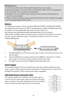
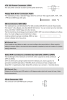
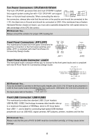
Fan Power Connectors: CPUFAN1/SYSFAN1 The 4-pin CPUFAN1 (processor fan) and 3-pin SYSFAN1 (system fan) support system cooling fan with +12V. CPUFAN1 can support three- or four-pin head connector. When connecting the wire to the connectors, always take note that the red wire is the positive and should be connected to the +12V, the black wire is Ground and should be connected to GND. If the mainboard has a System Hardware Monitor chipset on-board, you must use a specially designed fan with speed sensor to take advantage of the CPU fan control. MSI Reminds You... Always consult the vendors for proper CPU cooling fan. Front Panel Connectors: JFP1/JFP2 Power Power LED Switch The mainboard provides two front panel connectors for electrical connection to the front panel switches and LEDs. JFP1 is compliant with Intel Front Panel I/O 2 1 10 9 Connectivity Design Guide. HDD Reset LED Switch JFP1 Speaker 2 8 1 7 Power LED JFP2 Front Panel Audio Connector: JAUD1 The front panel audio connector allows you to connect to the front panel audio and is compliant with Intel ® Front Panel I/O Connectivity Design Guide. MSI Reminds You... If you do not want to connect to the front audio header, pins 5 & 6, 9 & 10 have to be jumpered in order to have signal output directed to the rear audio ports. Otherwise, the Line-Out connector on 9 1 the back panel will not function. 10 2 Front USB Connector: USB1/USB2 The mainboard provides two standard USB 2.0 pin headers USB1&USB2. USB2.0 technology increases data transfer rate up to a maximum throughput of 480Mbps, which is 40 times faster than USB 1.1, and is ideal for connecting high-speed USB interface peripherals such as USB HDD, digital cameras, MP3 players, printers, modems and the like. MSI Reminds You... Please note that the pins of VCC & GND must be connected correctly, or it may cause some damage 8
-
 1
1 -
2
-
3
-
4
-
5
-
6
-
 7
7 -
 8
8 -
 9
9 -
 10
10 -
 11
11 -
 12
12 -
 13
13 -
 14
14 -
 15
15 -
 16
16 -
 17
17 -
18
-
19
-
20
-
21
-
22
-
23
-
24
-
25
-
26
-
27
-
28
-
29
-
30
-
31
-
32
-
33
-
34
-
35
-
36
-
37
-
38
-
39
-
40
-
41
-
42
-
43
-
44
-
45
-
46
-
47
-
48
-
49
-
50
-
51
-
52
-
53
-
54
-
55
-
56
-
57
-
58
-
59
-
60
-
61
-
62
-
63
-
64
-
65
-
66
-
67
-
68
-
69
-
70
-
71
-
72
-
73
-
74
-
75
-
76
-
77
-
78
-
79
-
80
-
81
-
82
-
83
-
84
-
85
-
86
-
87
-
88
-
89
-
90
 |
 |
