MSI 865GVM3-V User Guide - Page 13
CNR Communication Network Riser Slot optional - bios settings
 |
UPC - 816909009958
View all MSI 865GVM3-V manuals
Add to My Manuals
Save this manual to your list of manuals |
Page 13 highlights
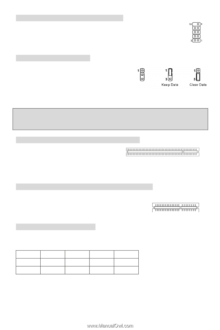
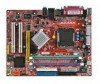
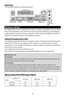
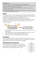
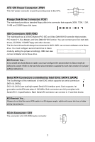
Serial Port Connector: JCOM2 (Optional) The mainboard offers one 9-pin male DIN connector COM A (on the rear panel), and one optional serial port JCOM2. Both are 16550A high speed communication ports that send/receive/ 16 bytes FIFOs. You can attach a serial mouse or other serial device directly to them. Clear CMOS Jumper: JBAT1 There is a CMOS RAM on board that has a power supply from external battery to keep the data of system configuration. With the CMOS RAM, the system can automatically boot OS every time it is turned on. If you want to clear the system configuration, use the JBAT1 (Clear CMOS Jumper) to clear data. Follow the instructions in the image to clear the data. MSI Reminds You... You can clear CMOS by shorting 2-3 pin while the system is off. Then return to 1-2 pin position. Avoid clearing the CMOS while the system is on; it will damage the mainboard. PCI (Peripheral Component Interconnect) Slots The PCI slots allow you to insert the expansion cards to meet your needs. When adding or removing expansion cards, make sure that you unplug the power supply first. Meanwhile, read the documentation for the expansion card to make any necessary hardware or software settings for the expansion card, such as jumpers, switches or BIOS configuration. CNR (Communication Network Riser) Slot (optional) The CNR slot allows you to insert the CNR expansion cards. CNR is a specially designed network, audio, or modem riser card for ATX family motherboards. Its main processing is done through software and controlled by the motherboard's chipset. PCI Interrupt Request Routing The IRQ, abbreviation of interrupt request line and pronounced I-R-Q, are hardware lines over which devices can send interrupt signals to the microprocessor. The PCI IRQ pins are typically connected to the PCI bus INT A# ~ INT D# pins as follows: Order1 Order2 Order3 Order4 PCI Slot 1 INT B# INT C# INT D# INT A# PCI Slot 2 INT C# INT D# INT A# INT B# 9
-
 1
1 -
2
-
3
-
4
-
5
-
6
-
7
-
 8
8 -
 9
9 -
 10
10 -
 11
11 -
 12
12 -
 13
13 -
 14
14 -
 15
15 -
 16
16 -
 17
17 -
 18
18 -
19
-
20
-
21
-
22
-
23
-
24
-
25
-
26
-
27
-
28
-
29
-
30
-
31
-
32
-
33
-
34
-
35
-
36
-
37
-
38
-
39
-
40
-
41
-
42
-
43
-
44
-
45
-
46
-
47
-
48
-
49
-
50
-
51
-
52
-
53
-
54
-
55
-
56
-
57
-
58
-
59
-
60
-
61
-
62
-
63
-
64
-
65
-
66
-
67
-
68
-
69
-
70
-
71
-
72
-
73
-
74
-
75
-
76
-
77
-
78
-
79
-
80
-
81
-
82
-
83
-
84
-
85
-
86
-
87
-
88
-
89
-
90
 |
 |