MSI G31TM-P21 User Guide - Page 12
ReaR PaneL, HaRdWaRe SetuP - memory
 |
UPC - 816909060331
View all MSI G31TM-P21 manuals
Add to My Manuals
Save this manual to your list of manuals |
Page 12 highlights
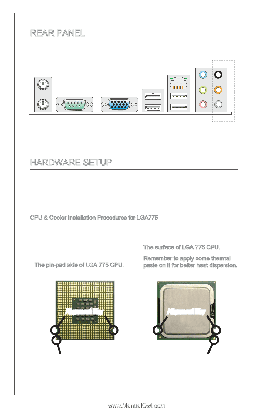
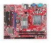
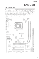
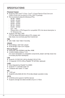
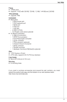
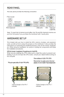
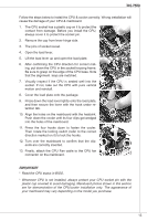
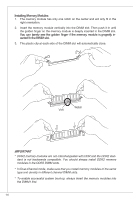
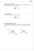
REAR PANEL The rear panel provides the following connectors: PS/2 mouse LAN Line-In RS-Out Serial port VGA port Line-Out CS-Out PS/2 keyboard USB ports MIC SS-Out (optional) Note: To reach the 8-channel sound effect, the 7th and 8th channels must be output from front panel if you purchase the mainboard with 3 audio jacks HARDWARE SETUP This chapter tells you how to install the CPU, memory modules, and expansion cards, as well as how to setup the jumpers on the mainboard. It also provides the instructions on connecting the peripheral devices, such as the mouse, keyboard, etc. While doing the installation, be careful in holding the components and follow the installation procedures. CPU & Cooler Installation Procedures for LGA775 When you are installing the CPU, make sure to install the cooler to prevent overheating. If you do not have the CPU cooler, consult your dealer before turning on the computer. The surface of LGA 775 CPU. The pin-pad side of LGA 775 CPU. Remember to apply some thermal paste on it for better heat dispersion. Alignment Key Alignment Key Yellow triangle is the Pin 1 indicator 12 Yellow triangle is the Pin 1 indicator
-
 1
1 -
2
-
3
-
4
-
5
-
6
-
 7
7 -
 8
8 -
 9
9 -
 10
10 -
 11
11 -
 12
12 -
 13
13 -
 14
14 -
 15
15 -
 16
16 -
 17
17 -
18
-
19
-
20
-
21
-
22
-
23
-
24
-
25
-
26
-
27
-
28
-
29
-
30
-
31
-
32
-
33
-
34
-
35
-
36
-
37
-
38
-
39
-
40
-
41
-
42
-
43
-
44
-
45
-
46
-
47
-
48
-
49
-
50
-
51
-
52
-
53
-
54
-
55
-
56
-
57
-
58
-
59
-
60
-
61
-
62
-
63
-
64
-
65
-
66
-
67
-
68
-
69
-
70
-
71
-
72
-
73
-
74
-
75
-
76
-
77
-
78
-
79
-
80
-
81
-
82
-
83
-
84
-
85
-
86
-
87
-
88
-
89
-
90
-
91
-
92
-
93
-
94
-
95
-
96
-
97
-
98
-
99
-
100
-
101
-
102
-
103
-
104
-
105
-
106
-
107
-
108
-
109
-
110
-
111
-
112
-
113
-
114
-
115
-
116
-
117
-
118
-
119
-
120
-
121
-
122
-
123
-
124
-
125
-
126
-
127
-
128
-
129
-
130
-
131
-
132
-
133
-
134
-
135
-
136
-
137
-
138
-
139
-
140
-
141
-
142
-
143
-
144
-
145
-
146
-
147
-
148
-
149
-
150
-
151
-
152
-
153
 |
 |