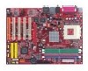
MSI KT880 User Guide - Page 6

Round Cable (Optional), Serial ATA/Serial ATA RAID Connectors controlled by VIA VT8237 - chipset

Page 6 highlights

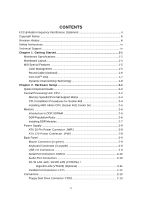
Fan Power Connectors: CFAN1 / SFAN1 / NBFAN1 2-13 ATA133 Hard Disk Connectors: IDE1 & IDE2 2-14 Serial ATA/Serial ATA RAID Connectors controlled by VIA VT8237: SATA1, SATA2 (Optional 2-15 Chassis Intrusion Switch Connector: J1 2-16 Front Panel Connectors: JFP1 & JFP2 2-16 CD-In Connector: JCD1 2-17 D-Bracket™ 2 Connector: JLED1 2-17 Front USB Connectors: JUSB1 & JUSB2 2-18 Front Panel Audio Connector: JAUD1 2-18 Jumper ...2-19 Clear CMOS Jumper: JBAT1 2-19 Slots ...2-20 AGP (Accelerated Graphics Port) Slot 2-20 PCI (Peripheral Component Interconnect) Slots 2-20 PCI Interrupt Request Routing 2-20 Chapter 3. BIOS Setup 3-1 Entering Setup ...3-2 Selecting the First Boot Device 3-2 Control Keys 3-3 Getting Help 3-3 Main Menu ...3-3 Default Settings 3-3 The Main Menu ...3-4 Standard CMOS Features 3-6 Advanced BIOS Features 3-8 Advanced Chipset Features 3-10 Integrated Peripherals 3-12 Power Management Features 3-15 PNP/PCI Configuration 3-18 H/W Monitor ...3-20 Cell Menu ...3-22 BIOS Setting Password 3-25 Load Fail-Safe/Optimized Defaults 3-26 Chapter 4. Introduction to DigiCell 4-1 Main ...4-2 H/W Diagnostic ...4-4 Communication ...4-5 vi

  • 1
  • 2
  • 3
  • 4
  • 5
  • 6
  • 7
  • 8
  • 9
  • 10
  • 11
  • 12
  • 13
  • 14
  • 15
  • 16
  • 17
  • 18
  • 19
  • 20
  • 21
  • 22
  • 23
  • 24
  • 25
  • 26
  • 27
  • 28
  • 29
  • 30
  • 31
  • 32
  • 33
  • 34
  • 35
  • 36
  • 37
  • 38
  • 39
  • 40
  • 41
  • 42
  • 43
  • 44
  • 45
  • 46
  • 47
  • 48
  • 49
  • 50
  • 51
  • 52
  • 53
  • 54
  • 55
  • 56
  • 57
  • 58
  • 59
  • 60
  • 61
  • 62
  • 63
  • 64
  • 65
  • 66
  • 67
  • 68
  • 69
  • 70
  • 71
  • 72
  • 73
  • 74
  • 75
  • 76
  • 77
  • 78
  • 79
  • 80
  • 81
  • 82
  • 83
  • 84
  • 85
  • 86
  • 87
  • 88
  • 89
  • 90
  • 91
  • 92
  • 93
  • 94
  • 95
  • 96
  • 97
  • 98
  • 99
  • 100
  • 101
  • 102
  • 103
  • 104
  • 105

vi
Fan Power Connectors: CFAN1 / SFAN1 / NBFAN1
.................................
2-13
ATA133 Hard Disk Connectors: IDE1 & IDE2
.............................................
2-14
Serial ATA/Serial ATA RAID Connectors controlled by VIA VT8237:
SATA1, SATA2 (Optional)
...................................................................
2-15
Chassis Intrusion Switch Connector: J1
...................................................
2-16
Front Panel Connectors: JFP1 & JFP2
.......................................................
2-16
CD-In Connector: JCD1
...............................................................................
2-17
D-Bracketâ„¢ 2 Connector: JLED1
...............................................................
2-17
Front USB Connectors: JUSB1 & JUSB2
...................................................
2-18
Front Panel Audio Connector: JAUD1
........................................................
2-18
Jumper
...............................................................................................................
2-19
Clear CMOS Jumper: JBAT1
.......................................................................
2-19
Slots
...............................................................................................................
2-20
AGP (Accelerated Graphics Port) Slot
......................................................
2-20
PCI (Peripheral Component Interconnect) Slots
........................................
2-20
PCI Interrupt Request Routing
....................................................................
2-20
Chapter 3. BIOS Setup
...........................................................................................
3-1
Entering Setup
.....................................................................................................
3-2
Selecting the First Boot Device
....................................................................
3-2
Control Keys
..................................................................................................
3-3
Getting Help
...................................................................................................
3-3
Main Menu
.....................................................................................................
3-3
Default Settings
.............................................................................................
3-3
The Main Menu
.....................................................................................................
3-4
Standard CMOS Features
...................................................................................
3-6
Advanced BIOS Features
...................................................................................
3-8
Advanced Chipset Features
.............................................................................
3-10
Integrated Peripherals
.......................................................................................
3-12
Power Management Features
..........................................................................
3-15
PNP/PCI Configuration
.......................................................................................
3-18
H/W Monitor
.......................................................................................................
3-20
Cell Menu
............................................................................................................
3-22
BIOS Setting Password
....................................................................................
3-25
Load Fail-Safe/Optimized Defaults
...................................................................
3-26
Chapter 4. Introduction to DigiCell
....................................................................
4-1
Main
.................................................................................................................
4-2
H/W Diagnostic
....................................................................................................
4-4
Communication
.....................................................................................................
4-5