MSI MS 7005 User Guide
MSI MS 7005 - 651M-L Motherboard - Micro ATX Manual
 |
UPC - 816909004229
View all MSI MS 7005 manuals
Add to My Manuals
Save this manual to your list of manuals |
MSI MS 7005 manual content summary:
- MSI MS 7005 | User Guide - Page 1
651M-L/650GM-L Series MS-7005 (v1.X) Micro ATX Mainboard Version 1.0 G52-M7005X1-K01 i - MSI MS 7005 | User Guide - Page 2
frequency energy and, if not installed and used in accordance with the instruction manual, may cause harmful interference to radio communications. Operation of this equipment AVANT DE RACCORDER AU RESEAU. Micro-Star International MS-7005 Tested to comply with FCC Standard For Home or Office Use ii - MSI MS 7005 | User Guide - Page 3
Microsoft is a registered trademark of Microsoft Corporation. Windows® 98/ 2000/NT/XP are registered trademarks of Microsoft Corporation. NVIDIA, the and CardBus are registered trademarks of the Personal Computer Memory Card International Association. Revision History Revision V1.0 Revision - MSI MS 7005 | User Guide - Page 4
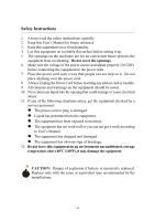
1. Always read the safety instructions carefully. 2. Keep this User's Manual for future reference. 3. Keep this equipment away shock. 11. If any of the following situations arises, get the equipment checked by a service personnel: z The power cord or plug is damaged. z Liquid has penetrated into the - MSI MS 7005 | User Guide - Page 5
Support iii Safety Instructions iv Chapter 1. Getting Started 1-1 Mainboard Specifications 1-2 Mainboard Layout 1-4 MSI Special Features 1-5 PC Alert™ 4 1-5 Live BIOS™/Live Driver 1-6 Live Monitor 1-7 Chapter 2. Hardware Setup 2-1 Quick Components Guide 2-2 Central Processing Unit: CPU - MSI MS 7005 | User Guide - Page 6
VGA Connector 2-12 RJ-45 LAN Jack 2-13 Audio Port Connectors 2-13 Midi/Joystick Connector 2-14 Parallel Port Interconnect) Slots 2-24 CNR Slot 2-24 PCI Interrupt Request Routing 2-25 Chapter 3. BIOS Setup 3-1 Entering Setup 3-2 Control Keys 3-2 Getting Help 3-3 The Main Menu 3-4 - MSI MS 7005 | User Guide - Page 7
Advanced BIOS Features 3-8 Advanced Chipset Features 3-12 Integrated Peripherals 3-14 Power Management or 6-Channel Audio Function A-1 Installing the Audio Driver A-2 Using 4- or 6-Channel Audio Function A-4 Testing the Connected Speakers A-8 Playing KaraOK A-10 Trouble shooting T-1 Glossary - MSI MS 7005 | User Guide - Page 8
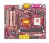
Hardware Setup Getting Started Thank you for purchasing 651M-L/650GM-L Series (MS-7005) v1.X Micro ATX mainboard. The 651M-L/650GM-L series is based on SiS® 651/650GX (702 pin BGA) & SiS® 962L MuTIOL Media I/O (371 BGA) chipsets and provides 6 USB 2.0 ports for high-speed data transmission. - MSI MS 7005 | User Guide - Page 9
MS-7005 Micro ATX Mainboard Mainboard Specifications CPU h Socket 478 for P4 processors (Willamette 478 / Northwood 478 / Celeron 478) at 400 MHz/ 533 MHz h Supports up to 3.06GHz. h Hyper-Threading CPU for SiS651 only. Chipset h SiS651/650GX (702 pin BGA) - High performance host interface 400 MHz/ - MSI MS 7005 | User Guide - Page 10
AC97 2.2 Spec - Meets PC2001 audio performance requirement LAN h SiS 962L integrated MAC + Realtek 8201BL PHY - Support 10Mb/s and 100Mb/s auto-negotiation operation. - Compliance with PCI 2.2 and PC99 standard. h Supports Wake-On-LAN and remote wake-up. h Supports ACPI power management. BIOS h 2MB - MSI MS 7005 | User Guide - Page 11
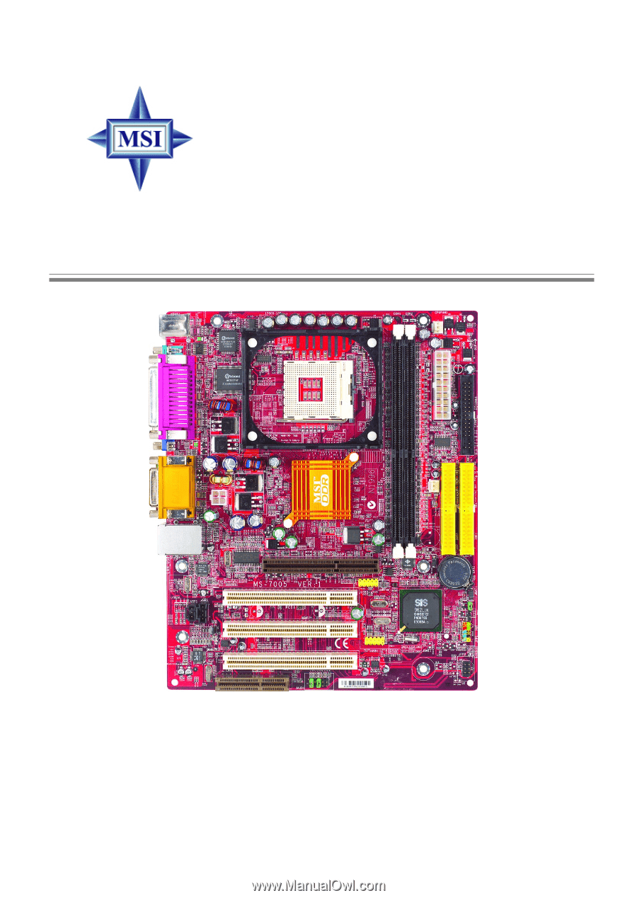
A VGA Port CPUFAN1 Top : Game port Bottom: Line-Out Line-In Mic AT X 1 2 V SiS 651/650GX T: LAN jack B: USB ports Realtek 8201BL JSP1 JCD1 AGP Slot PCI Slot 1 PCI Slot 2 JUSB2 Codec CNR PCI Slot 3 JAUD1 JUSB1 BATT + SiS 962L J BAT 1 JCI1 JFP1 JFP2 651M-L/650GM-L Series (MS-7005 - MSI MS 7005 | User Guide - Page 12
MSI Special Features PC Alert™ 4 The PC AlertTM 4 is a utility you can find in the CD-ROM disk. The utility is just like your PC doctor that can detect the following PC hardware status during real time operation: Ø monitor CPU Adjusting Keys temperature modes COOLER XP Users can use the Adjusting - MSI MS 7005 | User Guide - Page 13
MS-7005 Micro ATX Mainboard Live BIOS™/Live Driver™ The Live BIOS™/Live Driver™ is a tool used to detect and update your BIOS/drivers online so that you don't need to search for the correct BIOS/driver version throughout the Web site. To use the function, you need to install the "MSI Live Update 2" - MSI MS 7005 | User Guide - Page 14
™ The Live Monitor™ is a tool used to schedule the search for the latest BIOS/drivers version on the MSI Web site. To use the function, you need to install the "MSI Live Update 2" application. After the installation, the "MSI Live Monitor" icon (as shown on the right) will appear on the screen - MSI MS 7005 | User Guide - Page 15
Chapter 2. Hardware Setup Hardware Setup This chapter tells you how to install the CPU, memory modules, and expansion cards, as well as how to setup the jumpers on the mainboard. It also provides the instructions on connecting the peripheral devices, such as the mouse, keyboard, etc. While doing - MSI MS 7005 | User Guide - Page 16
MS-7005 Micro ATX Mainboard Quick Components Guide ATX12V, p.2-9 CPU, p.2-3 Back Panel I/O, p.2-10 DDR DIMMs, p.2-7 CPUFAN1, p.2-17 CONN1, p.2-9 FDD1, p.2-15 SYSFAN1, p.2-17 AGP Slot, p.2-24 JCD1, p.2-15 JSP1, p.2-21 PCI Slots, p.2-24 CNR Slot, p.2-24 + - MSI MS 7005 | User Guide - Page 17
speed = Host Clock x Core/Bus ratio = 100MHz x 17 = 1.7GHz Memory Speed/CPU FSB Support Matrix Memory FSB DDR 266 400 MHz OK 533 MHz OK DDR 333 OK OK MSI Reminds You... Overheating Overheating will seriously damage the CPU and system, always make sure the cooling fan can work properly to - MSI MS 7005 | User Guide - Page 18
MS-7005 Micro ATX Mainboard CPU Installation Procedures for Socket 478 1. Please turn off the power and unplug the power cord before installing the CPU. 2. Pull the lever sideways away from the socket. Make sure to raise the lever up to a 90degree angle. 3. Look for the gold arrow. The gold - MSI MS 7005 | User Guide - Page 19
heat, you need to attach the CPU cooling fan and heatsink on top of the CPU. Follow the instructions below to install the Heatsink/Fan: 1. Locate the CPU and its retention 2. Position the heatsink onto the reten- mechanism on the motherboard. tion mechanism. retention mechanism 3. Mount the - MSI MS 7005 | User Guide - Page 20
MS-7005 Micro ATX Mainboard 5. Connect the fan power cable from the mounted fan to the 3-pin fan power connec- tor on the board. fan power cable NOTES 2-6 - MSI MS 7005 | User Guide - Page 21
The mainboard provides two 184-pin unbuffered DDR200/DDR266/ DDR333 DDR SDRAM, and supports the memory size up to 2GB. To operate properly, at least one DIMM module must be installed. + DDR DIMM Slots (DDR 1~2) Introduction to DDR SDRAM DDR (Double - MSI MS 7005 | User Guide - Page 22
MS-7005 Micro ATX Mainboard DDR Module Combination Install at least one DIMM module on the slots. Memory modules can be installed on the slots in any order. You can install either single- or doublesided modules to meet your own needs. Memory modules can be installed in any combination as follows: - MSI MS 7005 | User Guide - Page 23
Hardware Setup Power Supply The mainboard supports ATX power supply for the power system. Before the connector. ATX 12V Power Connector: ATX12V This 12V power connector is used to provide power to the CPU. 11 1 42 31 ATX12V 20 10 CONN1 + ATX12V Pin Definition PIN SIGNAL 1 GND 2 GND - MSI MS 7005 | User Guide - Page 24
MS-7005 Micro ATX Mainboard Back Panel The back panel provides the following connectors: Mouse Parallel Midi/Joystick LAN Keyboard COMA VGA Port L-out L-in MIC USB Ports Mouse Connector The mainboard provides a standard PS/2® mouse mini DIN connector for attaching a PS/2® mouse. You can plug - MSI MS 7005 | User Guide - Page 25
Hardware Setup Keyboard Connector The mainboard provides a standard PS/2® keyboard mini DIN connector for attaching a PS/2® keyboard. You can plug a PS/2® keyboard directly into this connector. Pin Definition 6 5 PIN SIGNAL DESCRIPTION 1 4 3 2 3 2 1 4 PS/2 Keyboard (6-pin Female) 5 6 - MSI MS 7005 | User Guide - Page 26
MS-7005 Micro ATX Mainboard Serial Port Connectors: COMA The mainboard offers Set Ready Request To Send Clear To Send Ring Indicate VGA Connector The mainboard provides a DB 15-pin female connector to connect a VGA monitor. 5 1 15 11 VGA Connector (DB 15-pin) Pin Signal Description 1 RED - MSI MS 7005 | User Guide - Page 27
Line Out Line In MIC MSI Reminds You... For advanced audio application, Realtek ALC 655 is provided to offer support for 6-channel audio operation and can turn rear audio connectors from 2-channel to 4-/6-channel audio. For more information on 6-channel audio operation, please refer to Appendix - MSI MS 7005 | User Guide - Page 28
MS-7005 Micro ATX Mainboard Midi/Joystick Connector You can connect a joystick or game pad to this connector. Parallel Port Connector: LPT1 The mainboard provides a 25-pin female centronic connector as LPT. A parallel port is a standard printer port that supports Enhanced Parallel Port (EPP) and - MSI MS 7005 | User Guide - Page 29
connectors to connect to FDD, IDE HDD, case, LAN, USB Ports, IR module and CPU/System/Power Supply FAN. Floppy Disk Drive Connector: FDD1 The mainboard provides a standard floppy disk drive connector that supports 360K, 720K, 1.2M, 1.44M and 2.88M floppy disk types. FDD1 + CD-In Connector: JCD1 - MSI MS 7005 | User Guide - Page 30
MS-7005 Micro ATX Mainboard Hard Disk Connectors: IDE1 & IDE2 The mainboard has a the jumper accordingly. IDE2 (Secondary IDE Connector) IDE2 can also connect a Master and a Slave drive. MSI Reminds You... If you install two hard disks on cable, you must configure the second drive to Slave mode - MSI MS 7005 | User Guide - Page 31
use a specially designed fan with speed sensor to take advantage of the CPU fan control. GND +12V SENSOR CPUFAN1 GND +12V SENSOR SYSFAN1 + MSI Reminds You... 1. Always consult the vendors for proper CPU cooling fan. 2. CPUFAN1 supports the fan control. You can install the PC Alert utility that will - MSI MS 7005 | User Guide - Page 32
MS-7005 Micro ATX Mainboard Front Panel Connectors: JFP1 & JFP2 The mainboard provides two front panel connectors for electrical connection to the front panel switches and LEDs. JFP1 is compliant with Intel® Front Panel I/O Connectivity Design Guide. JFP1 12 HDD LED Reset Switch 9 10 Power LED - MSI MS 7005 | User Guide - Page 33
to control headphone amplifier 8 KEY No pin 9 AUD_FPOUT_L Left channel audio signal to front panel 10 AUD_RET_L Left channel audio signal return from front panel MSI Reminds You... If you don't want to connect to the front audio header, pins 5 & 6, 9 & 10 have to be jumpered in order to - MSI MS 7005 | User Guide - Page 34
MS-7005 Micro ATX Mainboard Front USB Connectors: JUSB1/JUSB2 The mainboard provides two USB 2.0 pin headers JUSB1 & JUSB2 that are compliant with Intel® I/O Connectivity Design Guide 10 2 JUSB2 (USB 2.0/Intel spec) + 2 10 1 9 JUSB1 (USB 2.0/Intel spec) JUSB1/2 Pin Definition PIN SIGNAL - MSI MS 7005 | User Guide - Page 35
) The connector is used to connect SPDIF (Sony & Philips Digital Interconnect Format) interface for digital audio transmission. JSP1 Pin Definition PIN SIGNAL 1 VCCS 2 SPDIF0 3 GND + 3 1 JSP1 The JSP1 supports SPDIF output only and can be connected to an external SPDIF Bracket for digital - MSI MS 7005 | User Guide - Page 36
MS-7005 Micro ATX Mainboard Chassis Intrusion Switch Connector: JCI1 This connector is connected to 2-pin connector chassis switch. If the Chassis is open, the switch will be short. The system will record this status. To clear the warning, you must enter the BIOS setting and clear the status. + JCI1 - MSI MS 7005 | User Guide - Page 37
computer's function. This section will explain how to change your motherboard's function through the use of jumpers. Clear CMOS Jumper: Jumper ) to clear data. Follow the instructions below to clear the data: 1 + JBAT1 1 1 3 Keep Data 3 Clear Data MSI Reminds You... You can clear CMOS by - MSI MS 7005 | User Guide - Page 38
MS-7005 Micro ATX Mainboard Slots The motherboard controller to directly access main memory. PCI (Peripheral Component Interconnect BIOS configuration. CNR slot The CNR slot allows you to insert the CNR expansion cards. CNR is a specially designed audio, or modem riser card for ATX family motherboards - MSI MS 7005 | User Guide - Page 39
Hardware Setup PCI Interrupt Request Routing The IRQ, abbreviation of interrupt request line and pronounced I-R-Q, are hardware lines over which devices can send interrupt signals to the microprocessor. The PCI IRQ pins are typically connected to the PCI bus INT A# ~ INT D# pins as follows: PCI - MSI MS 7005 | User Guide - Page 40
This chapter provides information on the BIOS Setup program and allows you to configure the system for optimum use. You may need to run the Setup program when: ” An error message appears - MSI MS 7005 | User Guide - Page 41
MS-7005 Micro ATX Mainboard Entering Setup Power on the computer and the system will start POST (Power On Self Test) process. When the message below appears - MSI MS 7005 | User Guide - Page 42
the appropriate keys to use and the possible selections for the highlighted item. Press to exit the Help screen. MSI Reminds You... The items under each BIOS category described in this chapter are under continuous update for better system performance. Therefore, the description may be slightly - MSI MS 7005 | User Guide - Page 43
MS-7005 Micro ATX Mainboard The Main Menu Once you enter Award® BIOS CMOS Setup Utility, the Main Menu (figure below) will appear on the for power management. PNP/PCI Configurations This entry appears if your system supports PnP/PCI. PC Health Status This entry shows your PC health status. 3-4 - MSI MS 7005 | User Guide - Page 44
Setup Frequency/Voltage Control Use this menu to specify your settings for frequency/voltage control. Load Fail-Safe Defaults Use this menu to load the BIOS values for the best system performance, but the system stability may be affected. Load Optimized Defaults Use this menu to load factory default - MSI MS 7005 | User Guide - Page 45
MS-7005 day month date year Day of the week, from Sun to Sat, determined by BIOS. Readonly. The month from Jan. through Dec. The date from 1 to second>. IDE Primary/Secondary Master/Slave Press PgUp/ or PgDn/ to select Manual, None or Auto type. Note that the specifications of your drive must - MSI MS 7005 | User Guide - Page 46
BIOS Setup If you select Manual, related information is asked to Support The item allows you to set the Floppy 3 Mode. Available options are: Disabled, Drive A, Drive B, Both. Video The setting controls the type of video adapter used for the primary monitor of the system. Available options: EGA/VGA - MSI MS 7005 | User Guide - Page 47
MS-7005 Micro ATX Mainboard Advanced BIOS Features Quick Boot Setting the item to Enabled allows the 1st/2nd/3rd Boot Device The items allow you to set the sequence of boot devices where BIOS attempts to load the disk operating system. The settings are: Floppy The system will boot from floppy - MSI MS 7005 | User Guide - Page 48
BIOS Setup HDD this sequence. MSI Reminds You... If you want to boot from any of the USB-interface devices, please set USB Keyboard/Mouse Support in SiS OnChip field is used to enable or disable the Intel Hyper Threading CPU function. Setting to Enabled will increase the system performance. Settings - MSI MS 7005 | User Guide - Page 49
MS-7005 Micro ATX Mainboard MSI Reminds You... Enabling the functionality of Hyper-Threading Technology for your computer system requires ALL of the following platform Components: *CPU: An Intel® Pentium® 4 Processor with HT Technology; *Chipset: A chipset that supports HT Technology; *BIOS: A BIOS - MSI MS 7005 | User Guide - Page 50
the type of BIOS password protection that (Advanced Programmable Interrupt Controller). Due to compliance to PC2001 design guide, the system is able to run in APIC mode. Enabling the operating system. You need to select the MPS version supported by your operating system. To find out which version to - MSI MS 7005 | User Guide - Page 51
MS-7005 Micro ATX Mainboard Advanced Chipset Features MSI rates may be required in certain system designs to support loose layouts or slower memory. Setting options: Safe Mode, Normal Mode, Fast automatically to be determined by BIOS based on the configurations on the SPD (Serial Presence Detect) EEPROM - MSI MS 7005 | User Guide - Page 52
BIOS allocated to AGP for video purposes. The aperture is a portion of the PCI memory address range dedicated to graphics memory address space. Host technology allows the CPU to write directly to the graphics card without passing anything through the system memory and improves the AGP 4X speed. - MSI MS 7005 | User Guide - Page 53
MS-7005 Micro ATX Mainboard Integrated Peripherals SiS OnChip IDE Device Press - MSI MS 7005 | User Guide - Page 54
it and the operating environment includes a DMA driver (Windows ME, XP or a third-party IDE bus master driver). If your hard drive and your system software both support Ultra DMA/33, Ultra DMA/66, Ultra DMA/100 and Ultra DMA/133, select Auto to enable BIOS support. Settings: Auto, Disabled. IDE DMA - MSI MS 7005 | User Guide - Page 55
MS-7005 Micro ATX Mainboard SiS S/W Modem This item is used to enable/disable the address and IRQ for the onboard Serial Port A (COM A)/Serial Port B (COM B). Selecting Auto allows BIOS to automatically determine the correct base I/O port address. Settings: Disabled, 3F8/IRQ4, 2F8/IRQ3, 3E8/IRQ4, - MSI MS 7005 | User Guide - Page 56
BIOS Setup SPP: EPP: ECP: ECP + EPP: Normal: Standard Parallel Port Enhanced which VGA card is your primary graphics adapter. Settings: PCI Slot, AGP. System Share Memory Size The system shares memory to the onboard VGA card. This setting controls the exact memory size shared to the VGA card. - MSI MS 7005 | User Guide - Page 57
MS-7005 Micro ATX Mainboard Power Management Setup Sleep State This item specifies the power saving modes for ACPI function. Options are: S1/POS S3/STR The S1 sleep mode is a low power state. In this state, no system context is lost (CPU or chipset) and hardware maintains all system context. The - MSI MS 7005 | User Guide - Page 58
BIOS Setup MODEM Use IRQ This setting names the interrupt request (IRQ) line assigned to the modem (if any) on your system. Activity of the selected - MSI MS 7005 | User Guide - Page 59
MS-7005 Micro ATX Mainboard MSI Reminds You... S3-related functions described in this section are available only when your BIOS supports S3 sleep mode. IRQ [3-7, 9-15], NMI; IRQ 8 Break Suspend These fields specify whether the system will be awakened from power saving modes when activity or - MSI MS 7005 | User Guide - Page 60
BIOS Setup Time (hh:mm:ss) Alarm When Resume By Alarm is set to Enabled, the field specifies the time for Resume By Alarm. Format is < - MSI MS 7005 | User Guide - Page 61
MS-7005 Micro ATX Mainboard PNP/PCI Configurations This section describes configuring the PCI bus system and PnP (Plug & Play) feature. PCI, or Peripheral Component Interconnect, is a system which allows I/O devices to operate at speeds nearing the speed the CPU Access Memory) is where the BIOS - MSI MS 7005 | User Guide - Page 62
BIOS Setup IRQ Resources The items are adjustable only when Resources Controlled By is set to Manual. Press and you PCI/VGA Palette Snoop When set to Enabled, multiple VGA devices operating on different buses can handle data from the CPU on each set of palette registers on every video device - MSI MS 7005 | User Guide - Page 63
all fans' speeds. Shutdown Temperature If the CPU temperature reaches the upper limit preset in this setting, the system will be shut down automatically. This helps you to prevent the CPU overheating problem. This item is available only when your OS supports this function, such as Windows ME. 3-24 - MSI MS 7005 | User Guide - Page 64
CPU ratio manually or use the default value of the motherboard manufacturer. Settings: Manual, Default CPU Clock Ratio End users can overclock the processor (only if the processor supports so) by specifying the CPU . If you do not have any EMI problem, leave the setting at Disabled for optimal system - MSI MS 7005 | User Guide - Page 65
MS-7005 Micro ATX Mainboard slight jitter can introduce a temporary boost in clock speed which may just cause your overclocked processor to lock up. CPU Frequency Use this item to select the appropriate clock frequency of the CPU host bus. Options are: 100MHz, 133MHz, Default. DRAM Frequency Use - MSI MS 7005 | User Guide - Page 66
options on the main menu allow users to restore all of the BIOS settings to the default Fail-Safe or Optimized values. The Optimized Defaults mainboard. The Fail-Safe Defaults are the default values set by the BIOS vendor for stable system performance. When you select Load Fail-Safe Defaults, a - MSI MS 7005 | User Guide - Page 67
MS-7005 Micro ATX Mainboard Set Supervisor/User Password When you select this function, a message as below will appear on the screen: Type the password, up to eight characters in length, and press . The password typed now will replace any previously set password from CMOS memory BIOS MSI - MSI MS 7005 | User Guide - Page 68
Using 4- or 6-Channel Audio Function The motherboard is equipped with Realtek ALC655 chip, which provides support for 6-channel audio output, including 2 and use 4-/6-channel audio function on the board. TOPICS Installing the Audio Driver A-2 Using 4-/6-Channel Audio Function A-4 Testing the - MSI MS 7005 | User Guide - Page 69
properly before you can get access to 4-/6-channel audio operations. Follow the procedures described below to install the drivers for different operating systems. Installation for Windows 98SE/ME/2000/XP For Windows® 2000, you must install Windows® 2000 Service Pack2 or later before installing the - MSI MS 7005 | User Guide - Page 70
Using 4- or 6-Channel Audio Function 3. Click Next to start installing files into the system. 4. Click Finish to restart the system. Select this option A-3 - MSI MS 7005 | User Guide - Page 71
MS-7005 Micro ATX Mainboard Using 4- or 6-Channel Audio Function After installing the audio driver, you are able to use the 4-/6-channel audio feature now. To enable 4- or 6-channel audio operation, first connect 4 or 6 speakers to the appropriate audio Click the audio icon from the window tray at - MSI MS 7005 | User Guide - Page 72
Using 4- or 6-Channel Audio Function A-5 - MSI MS 7005 | User Guide - Page 73
MS-7005 Micro ATX Mainboard Connecting the Speakers When you have set the Multi-Channel Audio Function mode properly in the software utility, connect your speakers to the correct phone jacks in accordance with the setting in software utility. „ 2-Channel Mode - MSI MS 7005 | User Guide - Page 74
function are converted to Line Out function when 4-Channel Mode for 6-Speaker Output is selected. 3 2 1 MSI Reminds You... If the Center and Subwoofer speaker exchange their audio channels when you play video or music on the computer, a converter may be required to exchange center and subwoofer - MSI MS 7005 | User Guide - Page 75
MS-7005 Micro ATX Mainboard Testing the Connected Speakers To ensure that 4- or 6-channel audio operation works properly Center Front Right Front Left Rear Right Rear Left Subwoofer MSI Reminds You... 6 speakers appear on the "Speaker Test" window only when you select "6-Channel Mode" in the " - MSI MS 7005 | User Guide - Page 76
Using 4- or 6-Channel Audio Function 4. While you are testing the speakers in 6-Channel Mode, if the sound com- ing from the center speaker and subwoofer is swapped, you should select Swap Center/Subwoofer Output to readjust these two channels. Select this function A-9 - MSI MS 7005 | User Guide - Page 77
MS-7005 Micro ATX Mainboard Playing KaraOK The KaraOK function will automatically remove human voice (lyrics) and leave melody for you to sing the song. Note that this function applies only for 2-channel audio operation. Playing KaraOK 1. Click the audio icon from the window tray at the lower-right - MSI MS 7005 | User Guide - Page 78
be able to find the Model number in between the PCI slots. For Example: MS-6368 or 845E Max (MS-6566E) Q: How do I identify the BIOS version? A: Upon boot-up, the 1st line appearing after the memory count is the BIOS version. It is usually in the format: A6380MS V1.0 091096 where: 1st digit refers - MSI MS 7005 | User Guide - Page 79
MS-7005 MicroATX Mainboard decide for yourself if upgrading to the new BIOS will be worth it. A word of advice, though, do not upgrade to the new BIOS, unless you really have to. Q: How can I update my BIOS? A: For Award BIOS, refer to http://www.msi.com.tw/html/support/bios/ note/award.htm For AMI - MSI MS 7005 | User Guide - Page 80
Troubleshooting Q: Where can I find the BIOS for my motherboard? A: 1. For Server motherboard, refer to http://www.msi.com.tw/program/sup port/bios/bos/spt_bos_list.php?kind=3 2. For Desktop motherboard, refer to http://www.msi.com.tw/program/ support/bios/bos/spt_bos_list.php?kind=1 Note: The BIOS - MSI MS 7005 | User Guide - Page 81
MS-7005 MicroATX Mainboard kind=1&CHIP=Archives&ID=4 & find your board according to the CPU type 2. For VGA card, refer to http://www.msi.com.tw/program/support/ manual/mnu/spt_mnu_list.php?kind=3 Note: The manual is subdivided as Geforce4, Geforce3, Geforce2 & Archives If your VGA is Geforce4 based - MSI MS 7005 | User Guide - Page 82
Troubleshooting 2. For VGA card, refer to http://www.msi.com.tw/program/support/driver/ dvr/spt_dvr_list.php?part=2 where the drivers are divided according to video drivers, capture drivers & others 3. For Server motherboard, refer to http://www.msi.com.tw/program/support/driver/dvr/spt_dvr_list.php - MSI MS 7005 | User Guide - Page 83
MS-7005 MicroATX Mainboard Q: Where can I get my motherboard repaired since it is not working? A: The normal procedure is to contact your reseller (the place you bought the board from) for repair/exchange. If the reseller for some reason cannot be contacted, then contact MSI distributor (http://www. - MSI MS 7005 | User Guide - Page 84
the source of the problem - Disable all on-board device like audio, RAID or other applications & see if it is due to resource conflict - Move the PCI card to different PCI slots - Update the card BIOS or drivers - Update the motherboard BIOS Q: What should I do if my MSI VGA card have compatibility - MSI MS 7005 | User Guide - Page 85
attached to the computer. Windows 98/98SE, Windows 2000 and Windows ME can fully support ACPI to allow users provides an interface between the OS and the components. The BIOS is stored in a ROM chip. Bus A set of to the CPU and main memory. Cache A special memory subsystem that is used to speed up - MSI MS 7005 | User Guide - Page 86
MS-7005 modern CPUs run much faster (up to 533 MHz), the CPU can execute several instructions in a single clock tick. CMOS (Complementary Metal-Oxide , DDR SDRAM, and RDRAM. For further instruction, please see the table below: Dynamic RAM (DRAM) Memory Technologies Type First Used FPM (60,70ns) - MSI MS 7005 | User Guide - Page 87
the old IDE standard. In addition, it can support mass storage devices of up to 8.4 gigabytes, whereas Windows and the BIOS access the ESCD area each time you re-boot your computer External Cache Short for Level 2 cache, cache memory that is external to the microprocessor. In general, L2 cache memory - MSI MS 7005 | User Guide - Page 88
MS-7005 supports data transfer rates of up to 400 Mbps for connecting up to 63 external devices. Internal Cache Short for Level 1 cache, a memory IRQ conflicts used to be a common problem when adding expansion boards, but the Plug motherboard. It allows 16 bits at a time to flow between the motherboard - MSI MS 7005 | User Guide - Page 89
disk drivers. LPT (Line Printer Terminal) Logical device name for a line printer; a name reserved by the MS- The PCI controller can exchange data with the system's CPU either 32 bits or 64 bits at a time. the system manually. To implement this useful feature, both the BIOS that supports PnP and - MSI MS 7005 | User Guide - Page 90
MS-7005 MicroATX Mainboard PS/2 Port A type of port developed by IBM for connecting a mouse or keyboard to a PC. The PS/2 port supports a mini DIN plug containing just 6 pins. Most modern PCs equipped with PS/2 ports so that the special port can be used by another device, such
-
 1
1 -
 2
2 -
 3
3 -
 4
4 -
 5
5 -
 6
6 -
 7
7 -
8
-
9
-
10
-
11
-
12
-
13
-
14
-
15
-
16
-
17
-
18
-
19
-
20
-
21
-
22
-
23
-
24
-
25
-
26
-
27
-
28
-
29
-
30
-
31
-
32
-
33
-
34
-
35
-
36
-
37
-
38
-
39
-
40
-
41
-
42
-
43
-
44
-
45
-
46
-
47
-
48
-
49
-
50
-
51
-
52
-
53
-
54
-
55
-
56
-
57
-
58
-
59
-
60
-
61
-
62
-
63
-
64
-
65
-
66
-
67
-
68
-
69
-
70
-
71
-
72
-
73
-
74
-
75
-
76
-
77
-
78
-
79
-
80
-
81
-
82
-
83
-
84
-
85
-
86
-
87
-
88
-
89
-
90
 |
 |
Version 1.0
G52-M7005X1-K01
651M-L/650GM-L Series
MS-7005 (v1.X) Micro ATX Mainboard