MSI P7N SLI-FI User Guide
MSI P7N SLI-FI - Motherboard - ATX Manual
 |
UPC - 816909045000
View all MSI P7N SLI-FI manuals
Add to My Manuals
Save this manual to your list of manuals |
MSI P7N SLI-FI manual content summary:
- MSI P7N SLI-FI | User Guide - Page 1
P7N SLI Series MS-7380 (v1.X) Mainboard G52-73801X5 i - MSI P7N SLI-FI | User Guide - Page 2
Technical Support If a problem arises with your system and no solution can be obtained from the user's manual, please contact your place of purchase or local distributor. Alternatively, please try the following help resources for further guidance. Visit the MSI website for FAQ, technical guide, BIOS - MSI P7N SLI-FI | User Guide - Page 3
1. Always read the safety instructions carefully. 2. Keep this User's Manual for future reference. 3. Keep this . 11. If any of the following situations arises, get the equipment checked by a service personnel: † The power cord or plug is damaged. † Liquid has penetrated into the equipment - MSI P7N SLI-FI | User Guide - Page 4
if not installed and used in accordance with the instructions, may cause harmful interference to radio communications. However, limits. VOIR LANOTICE D'INSTALLATIONAVANT DE RACCORDER AU RESEAU. Micro-Star International MS-7380 This device complies with Part 15 of the FCC Rules. Operation is subject - MSI P7N SLI-FI | User Guide - Page 5
WEEE (Waste Electrical and Electronic Equipment) Statement v - MSI P7N SLI-FI | User Guide - Page 6
vi - MSI P7N SLI-FI | User Guide - Page 7
vii - MSI P7N SLI-FI | User Guide - Page 8
Technical Support ...ii Safety Instructions ...iii Guide 2-2 CPU (Central Processing Unit 2-3 Memory ...2-7 Power Supply ...2-9 Back Panel ...2-11 Connectors ...2-13 Slots ...2-20 Chapter 3 BIOS BIOS Setting Password 3-25 Appendix A Realtek ALC888 Audio A-1 Installing the Realtek HD Audio Driver - MSI P7N SLI-FI | User Guide - Page 9
RAID B-1 Introduction ...B-2 RAID Configuraiton B-3 NVIDIA RAID Utility Installation B-9 RAID Drives Management B-12 Appendix C Dual Core Center C-1 Activating Dual Core Center C-2 Main ...C-3 DOT(Dyanmic OverClocking C-5 Clock ...C-6 Voltage ...C-7 FAN Speed ...C-8 Temperature ...C-9 User - MSI P7N SLI-FI | User Guide - Page 10
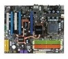
P7N SLI Series (MS-7380 v1.X) ATX mainboard. The P7N SLI Series mainboards are based on nVidia® nForce750i SLI & nForce430i chipsets for optimal system efficiency. Designed to fit the advanced Intel® Core 2 Extreme, Core 2 Quad, Core 2 Duo, Pentium dual-core and Celeron processor, the P7N SLI Series - MSI P7N SLI-FI | User Guide - Page 11
MS-7380 Mainboard Mainboard Specifications Processor Support - Intel® Core 2 Extrem e, Core 2 Quad, Core 2 Duo, Pentium dual- core and Celeron in the LGA775 package - Supports Intel® EIST Technology - Supports Intel® Hyper-Threading (HT) Technology (For the latest information about CPU, please visit - MSI P7N SLI-FI | User Guide - Page 12
Port pinheader (optional) Slots - 3 PCI Express x16 slots a. the mazarine PCI Express x 16 slot (PCI_E1) supports up to PCI Express 2.0 x16 b. two blue PCI Express x16 slots, each one supports up to PCIE 2.0 x8 c. supports SLI technology - 2 PCI slots, support 3.3V/ 5V PCI bus Interface Form Factor - MSI P7N SLI-FI | User Guide - Page 13
a l) PCI_E3 PC I 2 N v idi a BR04 N vi dia MCP51 FDD 1 VIA VT6308P (o p tio na l ) IDE 2 J1394_1 (o p ti on al ) JUSB1 IDE 1 J U SB2 DI M M 1 DI M M 2 DI M M 3 DI M M 4 B AT T + P7N SLI Series (MS-7380 v1.X) ATX Mainboard 1-4 JFP1 JFP2 - MSI P7N SLI-FI | User Guide - Page 14
Packing Checklist Getting Started MSI motherboard MSI Driver/Utility CD SLI Video Link Card Power Cable SATA Cable IDE Cable User's Guide Back IO Shield * The pictures are for reference only and may vary from the packing contents of the product you purchased. 1-5 - MSI P7N SLI-FI | User Guide - Page 15
Hardware Setup Chapter 2 Hardware Setup This chapter provides you with the information about hardware setup procedures. While doing the installation, be careful in holding the components and follow the installation procedures. For some components, if you install in the wrong orientation, the - MSI P7N SLI-FI | User Guide - Page 16
MS-7380 Mainboard Quick Components Guide SYSFAN1, p.2-15 CPU, p.2-3 JPWR2, p.2-9 CPUFAN1, p.2-15 Memroy DIMMs, p.2-7 Back Panel I/O, p.2-11 JCD1, p.2-16 JSPDIF, p.2-15 JCI1, p.2-16 JAUD1, p.2-16 PCI Express slots, p.2-20 JTPM, p.2-18 SYSFAN3, P2-15 PCI Slots, p.2-23 FDD1, p.2-14 JUSB1~2, - MSI P7N SLI-FI | User Guide - Page 17
, while doing overclocking. Any attempt to operate beyond product specifications is not recommended. We do not guarantee the damages or risks caused by inadequate operation or beyond product specifications. Introduction to LGA 775 CPU The pin-pad side of LGA 775 CPU. The surface of LGA 775 CPU - MSI P7N SLI-FI | User Guide - Page 18
MS-7380 Mainboard CPU & Cooler Installation W hen you are installing the CPU, make sure the CPU has a cooler attached on the top to prevent overheating. Meanwhile, do - MSI P7N SLI-FI | User Guide - Page 19
5. Lift the load lever up and open the load plate. Hardware Setup 6. After confirming the CPU direction for correct mating, put down the CPU in the socket housing frame. Be sure to grasp on the edge of the CPU base. Note that the alignment keys are matched. alignment key 7. Visually inspect if - MSI P7N SLI-FI | User Guide - Page 20
MS-7380 Mainboard 9. Press down the load lever lightly onto the load mainboard to confirm that the clip-ends are correctly inserted. locking switch Important 1. Read the CPU status in BIOS (Chapter 3). 2. Whenever CPU is not installed, always protect your CPU socket pin with the plastic cap - MSI P7N SLI-FI | User Guide - Page 21
Hardware Setup Memory These DIMM slots are used for installing memory modules. For more information on compatible components, please visit http://global.msi.com. tw/index.php?func=testreport DDR2 240-pin, 1.8V 56x2=112 pin 64x2=128 pin Dual-Channel Memory Population Rules In Dual-Channel mode, - MSI P7N SLI-FI | User Guide - Page 22
MS-7380 Mainboard Installing Memory Modules 1. The memory module has only one notch on the center and will only fit in the right orientation. 2. Insert the memory - MSI P7N SLI-FI | User Guide - Page 23
Hardware Setup Power Supply ATX 24-Pin Power Connector: JPWR1 This connector allows you to connect an ATX 24-pin power supply. To connect the ATX 24-pin power supply, make sure the plug of the power supply is inserted in the proper orientation and the pins are aligned. Then push down the power - MSI P7N SLI-FI | User Guide - Page 24
MS-7380 Mainboard Important Notification about Power Issue NForce chipset is very sensitive to ESD (Electrostatic Discharge), therefore this issue mostly happens while the users intensively swap memory modules under S5 (power-off) states, and the power code is plugged while installing modules. Due - MSI P7N SLI-FI | User Guide - Page 25
Back Panel Hardware Setup Mouse (optional) 1394 Port Keyboard Optical S/PDIF-Out LAN USB Port Line-In RS-Out Line-Out CS-Out Clear CMOS Button USB Port Mic SS-Out M ouse/K ey boar d The standard PS/2® mouse/keyboard DIN connector is for a PS/2® mouse/keyboard. 1394 Port (optional) The - MSI P7N SLI-FI | User Guide - Page 26
MS-7380 Mainboard USB Port The USB (Universal Serial Bus) port is for attaching USB devices such as keyboard, mouse, or other USB-compatible devices. LAN The standard RJ-45 LAN jack is for con- ActivityIndicator nection to the Local Area Network (LAN). You can connect a network cable to it. Link - MSI P7N SLI-FI | User Guide - Page 27
Hardware Setup Connectors IDE Connector: IDE1 / IDE2 This connector supports IDE hard disk drives, optical disk drives and other IDE devices. IDE2 IDE1 IDE1 (Primary IDE slave mode by setting jumpers. Refer to IDE device's documentation supplied by the vendors for jumper setting instructions. 2-13 - MSI P7N SLI-FI | User Guide - Page 28
MS-7380 Mainboard Floppy Disk Drive Connector: FDD1 This connector supports 360KB, 720KB, 1.2MB, 1.44MB or 2.88MB floppy disk drive. FDD1 Serial ATA Connector: SATA1_2/ SATA3_4 This connector is a high-speed Serial ATA interface port. Each - MSI P7N SLI-FI | User Guide - Page 29
Important 1. Please refer to the recommended CPU fans at processor's official website or consult the vendors for proper CPU cooling fan. 2. CPUFAN1 supports fan control. You can install Dual Core Center utility that will automatically control the CPU fan speed according to the actual CPU temperature - MSI P7N SLI-FI | User Guide - Page 30
MS-7380 Mainboard Front Panel Audio Connector: JAUD1 This connector allows you to connect the front panel audio and is compliant with Intel® Front Panel I/O Connectivity Design Guide the screen. To clear the warning, you must enter the BIOS utility and clear the record. 1 CINTRU GND JCI1 CD-In - MSI P7N SLI-FI | User Guide - Page 31
Hardware Setup Front USB Connector: JUSB1 / JUSB2 This connector, compliant with Intel® I/O Connectivity Design Guide, is ideal for connecting high-speed USB interface peripherals such as USB HDD, digital cameras, MP3 players, printers, modems and the like. 2 10 1 9 JUSB1 / JUSB2 - MSI P7N SLI-FI | User Guide - Page 32
MS-7380 Mainboard IEEE1394 Connector: J1394_1 (optional) This connector allows you to connect connects to a TPM (Trusted Platform Module) module (optional). Please refer to the TPM security platform manual for more details and usages. 2 14 1 13 JTPM Pin Signal Description 1 LCLK LPC clock - MSI P7N SLI-FI | User Guide - Page 33
are for electrical connection to the front panel switches and LEDs. The JFP1 is compliant with Intel® Front Panel I/O Connectivity Design Guide. JFP1 10 Power Switch + Power LED 2 9 + Reset - Switch - HDD 1 +LED JFP1 Pin Definition PIN SIGNAL 1 HD_LED + 2 FP PW R/SLP 3 HD_LED - 4 FP - MSI P7N SLI-FI | User Guide - Page 34
MS-7380 Mainboard Slots PCI (Peripheral Component Interconnect) Express Slots The PCI Express slot supports the PCI Express interface expansion card. The PCI Express 2.0 x 16 supports up to 8.0 GB/s transfer rate. The PCI Express 2.0 x 8 supports up to 4.0 GB/s transfer rate. Mazarine PCI Express - MSI P7N SLI-FI | User Guide - Page 35
this technology, the two GPU cards must be connected by an SLI Video Link card. SLI Video Link Card If you intend to use the SLI mode for better graphics performance, please refer to the following instructions. 1.Install two graphics cards on PCI Express x16 slots. W ith two cards installed, an - MSI P7N SLI-FI | User Guide - Page 36
MS-7380 Mainboard 2. After the hardware installation is completed, restart the system and install the NV SLI driver/utility. A configuration panel will be provided for Multi-GPU control. Check the Enable multi-GPU box to enable the SLI function for the onboard graphics cards (concerning the details - MSI P7N SLI-FI | User Guide - Page 37
PCI slots support LAN cards, SCSI cards, USB cards, and other add-on cards that comply with PCI specifications. At 32 bits and 33 MHz, it yields a throughput rate of 133 MBps. 32-bit PCI Slot PCI or software settings for the expansion card, such as jumpers, switches or BIOS configuration. 2-23 - MSI P7N SLI-FI | User Guide - Page 38
This chapter provides information on the BIOS Setup program and allows you to configure the system for optimum use. You may need to run the Setup program when: ² An error message appears - MSI P7N SLI-FI | User Guide - Page 39
MS-7380 Mainboard Entering Setup Power on the computer and the system will start to BIOS maker as A = AMI, W = AWARD, and P = PHOENIX. 2nd - 5th digit refers to the model number. 6th digit refers to the chipset as I = Intel, N = nVidia, and V = VIA. 7th - 8th digit refers to the customer as MS = - MSI P7N SLI-FI | User Guide - Page 40
BIOS Setup Control Keys Enter> Move to the sub-menu. If you want to return to the main menu, just press the . General Help The BIOS setup program provides a General Help screen. You can call up this screen from any menu by simply pressing . The - MSI P7N SLI-FI | User Guide - Page 41
. PnP/PCI Configurations This entry appears if your system supports PnP/PCI. H/W Monitor This entry shows your PC health status. BIOS Setting Password Use this menu to set the password for BIOS. Cell Menu Use this menu to specify your settings for frequency/voltage control and overclocking. 3-4 - MSI P7N SLI-FI | User Guide - Page 42
USER SETTINGS Use this menu to save/ load your settings to/ from CMOS for BIOS. Load Fail-Safe Defaults Use this menu to load the default values set by the BIOS vendor for stable system performance. Load Optimized Defaults Use this menu to load the default values set by the mainboard manufacturer - MSI P7N SLI-FI | User Guide - Page 43
MS-7380 Mainboard Standard CMOS Features The items in Standard CMOS Features Menu include The format is . day Day of the week, from Sun to Sat, determined by BIOS. Read-only. month The month from Jan. through Dec. date The date from 1 to 31 can be keyed by numeric - MSI P7N SLI-FI | User Guide - Page 44
BIOS Setup IDE Primary/ Secondary Master/ Slave, SATA 1/2/3/4 , E-SATA 1/2 It will showing the device informations that you connected to the IDE/SATA connector. LBA/Large M ode This allows you to enable or disable the LBA Mode. Setting to Auto enables LBA mode if the device supports it and the - MSI P7N SLI-FI | User Guide - Page 45
MS-7380 Mainboard Floppy Drive A This item allows you to set the type of floppy drives installed. Available options: [None], [360K to enter the sub-menu, and the following screen appears. This sub-menu shows the CPU information, BIOS version and memory status of your system (read only). 3-8 - MSI P7N SLI-FI | User Guide - Page 46
Advanced BIOS Features BIOS Setup Full (Advanced Programmable Interrupt Controller). Due to compliance with PC2001 design guide, the system is able to run in APIC mode. Enabling . You need to select the MPS version supported by your operating system. To find out which version to use, consult - MSI P7N SLI-FI | User Guide - Page 47
functionality can prevent certain classes of malicious "buffer overflow" attacks when combined with a supporting operating system. This functionality allows the processor to classify areas in memory by where application code can execute and where it cannot. W hen a malicious worm attempts to insert - MSI P7N SLI-FI | User Guide - Page 48
items allow you to set the first/ second/ third boot device where BIOS attempts to load the disk operating system. Boot From Other Device Setting to enter the sub-menu and the following screen appears: TCG/TPM SUPPORT Setting the option to [Yes] enables TPM (Trusted Platform Module) to the - MSI P7N SLI-FI | User Guide - Page 49
MS-7380 Mainboard Integrated Peripherals USB Controller This setting allows you to enable/disable the onboard USB controller. USB Device Legacy Support Select [Enabled] if you need to use a USB-interfaced device in the operating system. Onboard LAN Controller This item is used to enable/disable the - MSI P7N SLI-FI | User Guide - Page 50
menu and the following screen appears: On-Chip IDE Controller This item allows you to enable/ disable IDE Controller. PCI IDE BusMaster This item allows you to enable/ disable BIOS to use PCI busmastering for reading/ writing to IDE drives. On-Chip SATA Controller This item allows users to enable or - MSI P7N SLI-FI | User Guide - Page 51
MS-7380 Mainboard Power Management Setup Important S3-related functions described in this section are available only when your BIOS supports S3 sleep mode. ACPI Function This item can activate the ACPI (Advanced Configuration and Power Management Interface) Function. If your operating system is - MSI P7N SLI-FI | User Guide - Page 52
] allows BIOS to call VGABIOS to initialize the VGA card when system wakes up (resumes) from S3 sleep state. The system resume time is shortened when you disable the function, but system will need an VGA driver to initialize the VGA card. Therefore, if the VGA driver of the card does not support the - MSI P7N SLI-FI | User Guide - Page 53
MS-7380 Mainboard Resume By PCI Device (PM E#) W hen set to [Enabled], the feature allows your system to be awakened from the power saving modes through any event on PME (Power Management Event). Resume By PCI-E Device W hen set to [Enabled], the feature allows your system to be awakened from the - MSI P7N SLI-FI | User Guide - Page 54
H/W Monitor BIOS Setup Chassis Intrusion The field enables or disables the feature of recording the chassis intrusion status and issuing a warning message if the chassis is once - MSI P7N SLI-FI | User Guide - Page 55
MS-7380 Mainboard Cell Menu Important Change these settings only if you are familiar with the chipset. Current CPU/ FSB/ DRAM Frequency These items show the current clocks of CPU and Memory speed. Read-only. D.O.T. Control D.O.T. (Dynamic Overclocking Technology) is the automatic overclocking - MSI P7N SLI-FI | User Guide - Page 56
BIOS Setup [General] [Commander] 5th level of overclocking, increasing the frequency by 10%. 6th level of overclocking, increasing the frequency by 15%. Important Even though the Dynamic Overclocking Technology is more stable than manual overclocking, basically, it is still risky. We suggest user - MSI P7N SLI-FI | User Guide - Page 57
MS-7380 Mainboard CAS Latency(CL) W hen the Memory Timings sets to [Manual], the field is adjustable.This controls the CAS latency, which determines the timing delay (in clock cycles) before SDRAM starts a read command after receiving it. tRCD W hen the M emory Timings sets to [Manual], the field is - MSI P7N SLI-FI | User Guide - Page 58
Sourth Bridge voltage. Spread Spectrum W hen the motherboard's clock generator pulses, the extreme values (spikes) of the pulses create EMI ( clock speed which may just cause your overclocked processor to lock up. Important 1. If you do not have any EMI problem, leave the setting at [Disabled] for - MSI P7N SLI-FI | User Guide - Page 59
MS-7380 Mainboard CPU and Memory Clock Overclocking The D.O.T. Control/ FSB Clock/ Memory Clock are the items for you to overclock the CPU and the Memory. Please refer to the descriptions of these fields for more information. Important This motherboard supports overclocking greatly. However, please - MSI P7N SLI-FI | User Guide - Page 60
USER SETTINGS BIOS Setup Save Settings 1/ 2 These items are used to save the settings set by yourself to CMOS. Load Settings 1/ 2 These items are available after you save your settings in Save Settings 1/ 2 items , and are used to load the settings from CMOS. 3-23 - MSI P7N SLI-FI | User Guide - Page 61
MS-7380 Mainboard Load Fail-Safe/ Optimized Defaults The two options on the main menu allow users to restore all of the BIOS settings to the default Fail-Safe or Optimized values. The Optimized Defaults are the default values set by the mainboard manufacturer specifically for optimal performance - MSI P7N SLI-FI | User Guide - Page 62
BIOS Setup BIOS Setting Password W hen you select this function, a message as below will appear on the screen: Type the password, up to six characters in length, and - MSI P7N SLI-FI | User Guide - Page 63
Appendix A Realtek ALC888 Audio The Realtek ALC888 provides 10-channel DAC that simultaneously supports 7.1 sound playback and 2 channels of independent stereo sound output (multiple streaming) through the Front-Out-Left and Front-OutRight channels. - MSI P7N SLI-FI | User Guide - Page 64
MS-7380 Mainboard Installing the Realtek HD Audio Driver You need to install the HD audio driver for Realtek ALC888 codec to function properly before you can get access to 2-, 4-, 6-, 8- channel or 7.1+2 channel audio operations. Follow the procedures described below to install the drivers for - MSI P7N SLI-FI | User Guide - Page 65
Realtek ALC888 Audio 3. Click Next to install the Realtek High Definition Audio Driver. 4. Click Finish to restart the system. Click here Select this option Click here A-3 - MSI P7N SLI-FI | User Guide - Page 66
MS-7380 Mainboard Software Configuration After installing the audio driver, you are able to use the 2-, 4-, 6- or 8- channel audio feature now. Click the audio icon from the system tray at the lower-right corner of - MSI P7N SLI-FI | User Guide - Page 67
Realtek ALC888 Audio Sound Effect Here you can select a sound effect you like from the Environment list. Environment Simulation You will be able to enjoy different sound experience by pulling down the arrow, several kinds of sound effect will be shown for selection. Realtek HD Audio Sound Manager - MSI P7N SLI-FI | User Guide - Page 68
MS-7380 Mainboard Equalizer Selection Equalizer frees users from default settings; users may create their owned preferred settings by utilizing this tool. 10 bands of equalizer, ranging - MSI P7N SLI-FI | User Guide - Page 69
Realtek ALC888 Audio Frequently Used Equalizer Setting Realtek recognizes the needs that you might have. By leveraging our long experience at audio field, Realtek HD Audio Sound Manager provides you certain optimized equalizer settings that are frequently used for your quick enjoyment. [How to Use - MSI P7N SLI-FI | User Guide - Page 70
MS-7380 Mainboard Mixer In the Mixer part, you may adjust the volumes of the rear after you pluging the speakers into the jacks on the front panel. 2. Multi-Stream Function ALC888 supports an outstanding feature called Multi-Stream, which means you may play different audio sources simultaneously and - MSI P7N SLI-FI | User Guide - Page 71
Realtek ALC888 Audio W hen you are playing the first audio source (for example: use W indows Media Player to play DVD/VCD), the output will be played from the rear panel, which is the default setting. Then you must to select the Realtek HD Audio front output from the scroll list first, and use a - MSI P7N SLI-FI | User Guide - Page 72
MS-7380 Mainboard 3. Playback control Tool Mute Playback device This function is to let you freely decide which ports to output the sound. And this is essential - MSI P7N SLI-FI | User Guide - Page 73
4. Recording control Realtek ALC888 Audio Tool Mute Recording device -Back Line in/Mic, Front Lin in -Realtek HD Audio Input Mute You may choose to mute single or multiple volume controls or to completely mute sound input. Tool - Show the following volume controls This is to let you freely - MSI P7N SLI-FI | User Guide - Page 74
MS-7380 Mainboard Audio I/O In this tab, you can easily configure your multi-channel audio function and speakers. You can choose a desired jack changed to the one that is same as your device. - If not correct, Realtek HD Audio Manager will guide you to plug the device into the correct jack. A-12 - MSI P7N SLI-FI | User Guide - Page 75
Connector Settings Click to access connector settings. Realtek ALC888 Audio Disable front panel jack detection (option) Find no function on front panel jacks? Please check if front jacks on your system are so-called AC'97 jacks. If so, please check this item to disable front panel jack detection - MSI P7N SLI-FI | User Guide - Page 76
MS-7380 Mainboard S/PDIF Short for Sony/Philips Digital Interface, a standard audio file transfer format. S/PDIF allows the transfer of digital audio signals from one device to - MSI P7N SLI-FI | User Guide - Page 77
Realtek ALC888 Audio Test Speakers You can select the speaker by clicking it to test its functionality. The one you select will light up and make testing sound. If any speaker fails to make sound, then check whether the cable is inserted firmly to the connector or replace the bad speakers with - MSI P7N SLI-FI | User Guide - Page 78
MS-7380 Mainboard Microphone In this tab you may set the function of the microphone. Select the Noise Suppression to remove the possible noise during recording, or - MSI P7N SLI-FI | User Guide - Page 79
Realtek ALC888 Audio 3D Audio Demo In this tab you may adjust your 3D positional audio before playing 3D audio applications like gaming. You may also select different environment to choose the most suitable environment you like. A-17 - MSI P7N SLI-FI | User Guide - Page 80
MS-7380 Mainboard Information In this tab it provides some information about this HD Audio Configuration utility, including Audio Driver Version, DirectX Version, Audio Controller & Audio Codec. You may also select the language of this utility by choosing from the Language list. Also there is a - MSI P7N SLI-FI | User Guide - Page 81
Realtek ALC888 Audio Hardware Setup Connecting the Speakers W hen you have set the Multi-Channel Audio Function mode properly in the software utility, connect your speakers to the correct phone jacks in accordance with the setting in software utility. n 2-Channel Mode for Stereo-Speaker Output 1 4 - MSI P7N SLI-FI | User Guide - Page 82
MS-7380 Mainboard n 4-Channel Mode for 4-Speaker Output 1 4 2 5 3 6 1 Line In 2 Line Out (Front channels) 3 MIC 4 Line Out (Rear channels) 5 No function 6 No function A-20 - MSI P7N SLI-FI | User Guide - Page 83
Realtek ALC888 Audio n 6-Channel Mode for 6-Speaker Output 1 4 2 5 3 6 1 Line In 2 Line Out (Front channels) 3 MIC 4 Line Out (Rear channels) 5 Line Out (Center and Subwoofer channel) 6 No function A-21 - MSI P7N SLI-FI | User Guide - Page 84
MS-7380 Mainboard n 8-Channel Mode for 8-Speaker Output 1 4 2 5 3 6 1 Line In 2 Line Out (Front channels) 3 MIC 4 Line Out (Rear channel audio-out function on Vista operating system, you have to install the Realtek Audio Driver. Or, the mainboard will support 5.1 channel audio-out only. A-22 - MSI P7N SLI-FI | User Guide - Page 85
Appendix B nVidia RAID nVidia RAID NVIDIA brings Redundant Array of Independent Disks (RAID) technology-which is used by the world's leading businesses-to the common PC desktop. This tech- nology uses - MSI P7N SLI-FI | User Guide - Page 86
MS-7380 Mainboard Introduction System Requirement Operating System Support NVRAID supports the following operating systems: W indows XP/ 2000 & Vista RAID Arrays NVRAID supports the following types of RAID arrays described in this section: RAID 0: RAID 0 defines a disk striping scheme that improves - MSI P7N SLI-FI | User Guide - Page 87
and create the desired RAID array. 3. Boot from the W indows CD, use the floppy disk that has the RAID driver to copy and install the nForce RAID software. (Check p.B-7 for details.) 4. Initialize the NVRAID Array Disks. Setting Up the NVRAID BIOS Be sure to enable the RAID mode for SATA devices in - MSI P7N SLI-FI | User Guide - Page 88
MS-7380 Mainboard Understanding the "Define a New Array" Window Use the Define a New Array window to • Select the RAID Mode • Set up the Striping Block • Specify which - MSI P7N SLI-FI | User Guide - Page 89
nVidia RAID Using the Define a New Array Window If necessary, press the tab key be between [4 KB] and [128 KB]. • Assigning the Disks The disks that you enabled from the RAID Config BIOS setup page appear in the Free Disks block. These are the drives that are available for use as RAID array disks. - MSI P7N SLI-FI | User Guide - Page 90
MS-7380 Mainboard Completing the RAID BIOS as RAID drives. The Array List window appears, where you can review the RAID arrays that you have set up. 3. Use the arrow RAID BIOS, the next step is to configure and load NVRAID drivers under W indows, as explained in "Installing the NVIDIA RAID Software Under - MSI P7N SLI-FI | User Guide - Page 91
the instruction below to make an nVIDIA Serial ATA RAID driver for yourself. 1. Insert the MSI CD driver disk for nVIDIA RAID controller is done. (2) Select "NVIDIA RAID CLASS DRIVER" and then press Enter. (3) Press S again at the Specify Devices screen, then press Enter. (4) Select "NVIDIA NForce - MSI P7N SLI-FI | User Guide - Page 92
MS-7380 Mainboard 4. Press Enter to continue with W indows XP Installation. Be sure to leave the floppy disk inserted in the floppy drive until the blue screen portion of W indows XP installation is completed, then take out the floppy. 5. Follow the instructions on how to install W indows XP. After - MSI P7N SLI-FI | User Guide - Page 93
the setup application and install the RAID software which will upgrade the W indows IDE driver and install the RAID software. 1. Start the NVIDIA nForce Drivers installation program to open the NVIDIA W indows nForce Drivers page. 2. Select the modules that you want to install. Make sure that the - MSI P7N SLI-FI | User Guide - Page 94
MS-7380 Mainboard Initializing and Using the Disk Array The RAID array is now ready to be initialized under W indows. 1. Launch Computer Management by clicking "Start" --> "Settings" --> " - MSI P7N SLI-FI | User Guide - Page 95
nVidia RAID 5. Check the disk in the list if you want to make the array a dynamic disk, then click Next. The Completing the Initialize and Convert - MSI P7N SLI-FI | User Guide - Page 96
MS-7380 Mainboard RAID Drives Management There is an application called NVRAIDMAN which helps you perform the following tasks of nVDIA RAID. • Viewing RAID Array Configurations View an array configuration (mirrored, striped, mirror-striped, JBOD, or any supported combination) • Setting Up a Spare - MSI P7N SLI-FI | User Guide - Page 97
nVidia RAID Setting Up a Spare RAID Disk You can designate a hard drive to be used as a spare drive for a RAID 1, RAID 0+1 or RAID 5 array. The spare drive can take over for a failed disk. NVRAID supports any array, 1. Enter the system BIOS setup and make sure that the drive that you want to mark - MSI P7N SLI-FI | User Guide - Page 98
MS-7380 Mainboard Assigning a Dedicated Disk To mark a disk as dedicated, or reserve it for use by a specific array, Step 1: Mark the Disk as a Free Disk 1. Enter the system BIOS setup and make sure that the drive that you want to mark as free is RAID enabled. 2. Boot into W indows and run the - MSI P7N SLI-FI | User Guide - Page 99
one of the two free disks available. This would be the disk that will be designated to the mirror array. 5. Click Next. The Completing the NVIDIA Spare Disk Allocation page appears. 6. Click Finish. As shown in figure below, the ST380011A drive is now a dedicated free disk in the mirrored array. If - MSI P7N SLI-FI | User Guide - Page 100
MS-7380 Mainboard Removing a Dedicated Disk Once a dedicated disk has been assigned to a particular array, it can be removed at any time. To remove the disk, right - MSI P7N SLI-FI | User Guide - Page 101
Morphing process and explains how to use Morphing to convert from one RAID array type to another. General Morphing Principles NVIDIA RAID includes extensive support for morphing, a process of converting from one RAID mode to another RAID mode. General Requirements and Limitations • The new array - MSI P7N SLI-FI | User Guide - Page 102
MS-7380 Mainboard From RAID 0+1 RAID 5 To RAID 0 RAID 1 RAID 0+1 RAID 5 RAID 0 RAID to a system safely and without causing problems for the RAID software. For example, when a drive in a mirrored array fails, the user can launch the Hot Plug Array W izard which instructs the user as to when a drive - MSI P7N SLI-FI | User Guide - Page 103
Click Next and the following screen shot will appear: nVidia RAID 3 Connect the RAID disk that you want to of newly configured RAID arrays is recommended to ensure consistency and reliable performance on any supported fault tolerant array such asRAID 5, RAID 0, and RAID 0+1. Use this feature only - MSI P7N SLI-FI | User Guide - Page 104
MS-7380 Mainboard 1 From the NVRAIDMAN window, right click on any available free disk and select Create Array as show in Figure below. 2 The Create Array W izard - MSI P7N SLI-FI | User Guide - Page 105
System Data screen appears again with the Initialize Array check box checked as shown below. 9 Click Next, then click Finish at the Completing the NVIDIA Create Array W izard screen. The NVRAIDMAN windows shows the created RAID array as shown below. The Initialization Process As you can see from the - MSI P7N SLI-FI | User Guide - Page 106
MS-7380 Mainboard Rebuilding a RAID Array Rebuilding is the process of restoring on the newly added drive. Rebuilding Instructions After creating a mirrored array, you can rebuild the array using the following steps: 1. Go to W indows and run the NVIDIA RAID Management utility. The picture below - MSI P7N SLI-FI | User Guide - Page 107
RAID 5. Select the drive that you want to rebuild by clicking it from the list, then click Next. The Completing the NVIDIA Rebuild Array page appears. 6. Click Finish. The array rebuilding starts after a few seconds, and a small pop-up message appears towards the bottom right corner of - MSI P7N SLI-FI | User Guide - Page 108
MS-7380 Mainboard During the rebuilding process, the NVRAID Management utility screen shows the status under the System Tasks and Details sections. M ore About Rebuilding Arrays • Rebuilding - MSI P7N SLI-FI | User Guide - Page 109
nVidia RAID Synchronizing a RAID Array Synchronizing an array will force a rebuild of redundancy or parity. The operation is applicable to any fault tolerant array such as - MSI P7N SLI-FI | User Guide - Page 110
Mainboard & MSI Graphics card in windows, such as CPU/GPU clock, voltage, fan speed and temperature. Before you install the Dual CoreCenter, please make sure the system has meet the following requirements: 1. Intel Pentium4 / Celeron, AMD Athlon XP/ Sempron or compatible CPU with PCI Express slot - MSI P7N SLI-FI | User Guide - Page 111
MS-7380 Mainboard Activating Dual Core Center Once you have your Dual Core Center installed (locate the setup source file in the setup CD accompanying with your mainboard, path: Utility --> MSI Utility --> Dual Core Center), it will have an icon in the system tray, a short cut icon on the - MSI P7N SLI-FI | User Guide - Page 112
using this utility, we have to remind you: only when installing the MSI V044 (V044 has to install with the version 8.26 or newer driver)/ V046 or V060 graphics card can activate the full function of this utility DOT Click DOT button to enable or disable the Dynamic Overclocking Technology. C-3 - MSI P7N SLI-FI | User Guide - Page 113
MS-7380 Mainboard AV/ Game/ Office/ Silence/ Cool MSI provides five common settings for different environments. The settings had been set to optimal values to reach better performance in each environment. Click the button - MSI P7N SLI-FI | User Guide - Page 114
Overclocking Technology will be powered only when users' PC runs huge amount of data, like 3D games or video process, and the motherboard/ DOWN Rate button Important Even though the Dynamic Overclocking Technology is more stable than manual overclocking, basically, it is still risky. We suggest user - MSI P7N SLI-FI | User Guide - Page 115
MS-7380 Mainboard Clock In the Clock sub-menu, you can see clock status (including FSB/ CPU clock of mainboard and GPU/ memory clock of graphics card) of your system. And you can select desired value for overclocking. There will be several items for you to select for overclocking after you - MSI P7N SLI-FI | User Guide - Page 116
see voltage status (including Vcore, memory, GPU I voltage... etc.) of your system, and you can select desired value for overclocking. It will show several items to select for overclocking after you click the button. You can click the plus sign button to increase the voltage, or click the minus - MSI P7N SLI-FI | User Guide - Page 117
MS-7380 Mainboard FAN Speed In the FAN Speed sub-menu, you can read fan with red color will be shown. Important 1. When you set the fan speed manually, please make sure to disabled the "CPU Smart FAN Target" item in the BIOS. 2. In the user profile, clicking the Save button can save the changes - MSI P7N SLI-FI | User Guide - Page 118
Dual Core Center Temperature In the Temperature sub-menu, you can see temperature status of your system. On the underside, it shows the graphs of the temperatures. Only the curves of the item which the button is lit up with red color will be shown. C-9 - MSI P7N SLI-FI | User Guide - Page 119
MS-7380 Mainboard User Profile In the User Profile sub-menu, click the setting button that besides the user profile bar, and the next screen will appear. - MSI P7N SLI-FI | User Guide - Page 120
Dual Core Center Use the draw bar to set the max system temperature. W hen the system temperature exceeds the threshold you defined, the system will pop up a warning message and shut down the system. Use the draw bar to set the minimal fan speed. When the fan speed is lower than the threshold you
-
 1
1 -
 2
2 -
 3
3 -
 4
4 -
 5
5 -
 6
6 -
 7
7 -
8
-
9
-
10
-
11
-
12
-
13
-
14
-
15
-
16
-
17
-
18
-
19
-
20
-
21
-
22
-
23
-
24
-
25
-
26
-
27
-
28
-
29
-
30
-
31
-
32
-
33
-
34
-
35
-
36
-
37
-
38
-
39
-
40
-
41
-
42
-
43
-
44
-
45
-
46
-
47
-
48
-
49
-
50
-
51
-
52
-
53
-
54
-
55
-
56
-
57
-
58
-
59
-
60
-
61
-
62
-
63
-
64
-
65
-
66
-
67
-
68
-
69
-
70
-
71
-
72
-
73
-
74
-
75
-
76
-
77
-
78
-
79
-
80
-
81
-
82
-
83
-
84
-
85
-
86
-
87
-
88
-
89
-
90
-
91
-
92
-
93
-
94
-
95
-
96
-
97
-
98
-
99
-
100
-
101
-
102
-
103
-
104
-
105
-
106
-
107
-
108
-
109
-
110
-
111
-
112
-
113
-
114
-
115
-
116
-
117
-
118
-
119
-
120
 |
 |
P7N SLI Series
MS-7380 (v1.X) Mainboard
G52-73801X5