Mackie SR244 / SR324 Contractor's Specs - Page 4
The SR Series consoles
 |
View all Mackie SR244 / SR324 manuals
Add to My Manuals
Save this manual to your list of manuals |
Page 4 highlights
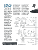
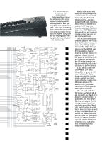
The main chassis of the SR24•4 and SR32•4 mixing consoles is made of solid steel monocoque construction. Because the steel doesn't flex, the console itself is quite sturdy. And at the same time, the SR Series consoles don't weigh a ton, either. Controls are designed to withstand serious downward impact. From a fistpounding to a heavy box dropping, the SR Series' knobs can take it. We also use sealed controls rather than open-frame potentiometers that eventually deteriorate from airborne contamination. Switches are ultra-high duty-cycle. And inside, impact-resistant, double-thru-hole-plated fiberglass circuit boards, brass standoffs, and gold-plated interconnects abound. The SR24•4 and 32•4's 60mm faders are made with the same precision log taper as those on our 8•Bus consoles. Besides giving smooth, consistent fades, these faders were built to last. They have a newly-developed, ultra-tight lip seal made of a special co-polymer membrane that provides a continuouslysealed barrier against dust and liquid, yet doesn't interfere with fader travel. There's more. 1/4" jack sleeves are metal, not plastic. That's part of the reason why the SR24•4 and 32•4 have such exceptional protection from RF interfer- The SR Series consoles ence. (As you well know, have built-in power sup- many installations suffer plies (instead of a "wall from such problems.) wart," which takes up pre- Metal lockwashers make cious outlet spaces and can ® electrical contact between get lost or damaged), so the jack and outer chassis, you're sure to have plenty and an internal shunting of power. We could go on capacitor is placed from and on, but suffice to say each input to ground. This that people who have routes RF back through the hauled their SR24•4s and metal chassis, where it is 32•4s all over the country dissipated before it can will attest to their durability. propagate via the SR24•4 They'll hold up to years of or 32•4's circuit boards. use with nary a problem. Vp 1 MIC • IN LINE IN PHANTOM POWER (GLOBAL SWITCH) • INSERT • • 2• • 3 MACKIE MIC PREAMP • • •+ •- 75Hz HPF TRIM: MIC GAIN- LO CUT MUTE +10 to +60 dB LINE GAIN- -10 to +40 dB BOLD LINES INDICATE SIGNAL PATH FROM MIC INPUT TO LEFT MAIN OUTPUT. MONO INPUT CHANNEL SR 24•4 (1 of 20) SR32•4 (1 of 32) • • • • • • AUX 1 AUX 2 PRE AUX 3 AUX 4 AUX 5 AUX 6 -20 dB LED O/L LED ASSIGN SWITCHES EQ • LO MID HI 10080 8k 12k PAN •• • FADER • •• • •• GAIN FREQ FREQ GAIN • •• 1-2 • • 3-4 • L-R • • MUTE LED (STEADY) SOLO LED (FLASHING) SOLO IN PLACE PFL LOGIC • LEFT (MONO) RIGHT + •• - • • TRIM MUTE -20dB LED +• - LINE GAIN-20 TO +20dB • • LO LO- HI- HI MID MID 80 800 3k 12k •• O/L LED • LO LO- HI- HI MID MID • 80 800 3k 12k MUTE LED • (STEADY) SOLO LED • (FLASHING FADER • PAN • •• • • • 1-2 • • 3-4 • • L-R • SOLO IN PLACE PFL LOGIC STEREO INPUT CHANNEL (1 OF 2) • • • •• • AUX 1 AUX 2 PRE AUX 3 AUX 4 AUX 5 AUX 6 EXIT 27B STOPLIGHT 316 GLENDALE (KNOCK FIRST) •• • • TALKBACK XLR INPUT LEVEL • TB TO AUX 1-2 • • • MACKIE SR24•4/SR32•4 BLOCK DIAGRAM Rev. 1.5 5/11/95 • • TB TO L-R MIX • SUB 1 SUB 2 SUB 3 SUB 4 L MIX R MIX
-
 1
1 -
 2
2 -
 3
3 -
 4
4 -
 5
5 -
 6
6
 |
 |
