Mackie SR244 VLZ Pro / SR324 VLZ Pro VLZ Pro Owner's Manual - Page 6
Quick Start
 |
View all Mackie SR244 VLZ Pro / SR324 VLZ Pro manuals
Add to My Manuals
Save this manual to your list of manuals |
Page 6 highlights
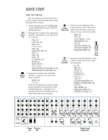
QUICK START OO OO ZERO THE CONSOLE Note: the numbers in brackets refer to the numbers inside each switch and control in the drawing on the next page. 1. On the rear panel, turn the POWER switch and the PHANTOM off, and the OUTPUT LEVEL fully down. 2. Disengage these switches (for pushbutton Switch switches, "disengaged" or "off" refers to the Up "up" position): PRE (27) LOW CUT (34) SOLO (39) 1-2 & 3-4 (40) SOLO (47) ASSIGN TO SUB (50) SUB (51) SOLO (52) SOLO (57) L/R ASSIGN (59) MODE (63) MAIN MIX (67) AUX 1-2 (68) TAPE RETURN TO PHONES/C-R (69) TAPE RETURN TO MAIN MIX (71) 3. Engage these switches (for pushbutton Switch switches, "engaged" or "on" refers to the Down "down" position): MUTE (38) L-R (41) When we say engaged, this does not imply that you should become betrothed in any legally binding sense, although there is probably some drive-in wedding chapel in 'Vegas, where this can be arranged. 4. Set these controls fully down (for Control rotary controls, "down" refers to the Fully Down fully counter-clockwise position; for faders, it refers to all the way down): TRIM (25) AUX (26) TO AUX SEND 1-2 (49) TAPE RETURN (53) 20 AIR (56) 30 CHANNEL FADER (42) 40 50 SUBGROUP FADER (60) 60 MAIN MIX FADER (72) Fader Down 5. Set these controls at unity (for rotary Control controls, "unity" refers to the center Centered detent position. HI (28) MID (29) FREQ (30) HI MID (31) LOW MID (32) LOW (33) PAN (37) AUX SEND MASTERS (46) STEREO AUX RETURNS (48) PAN (58) SOLO LEVEL (62) TALKBACK LEVEL (66) PHONES/C-R LEVEL (70) MAIN OUTS (BAL OR UNBAL) 1 L AUX SENDS (BAL OR UNBAL) STEREO AUX RETURNS (BAL OR UNBAL) 4R 1 L1 SUB OUTS (BAL OR UNBAL) SUB INSERTS (BAL OR UNBAL) 51 L 23 2 R 5R L2 2 62 MONO R 21 L MONO R 20 INSERT 19 INSERT 18 INSERT 17 INSERT 16 INSERT 15 INSERT 14 INSERT 3 L 6R 3 L3 R (BAL OR UNBAL) L R L4 4 R MAIN INSERTS 120VAC 50/60 HZ 60W 1A/250V SLO BLO FUSE INSIDE CONTROL ROOM OUT POWER ON (MONO) PHANTOM ON CAUTION: TO REDUCE THE RISK OF FIRE, REPLACE WITH THE SAME TYPE FUSE AND RATING OFF OFF 73 84 24 L 22 L LINE IN (BAL OR UNBAL) MIC 20 XDR MIC PRE LINE IN (BAL OR UNBAL) MIC 19 XDR MIC PRE LINE IN (BAL OR UNBAL) MIC 18 XDR MIC PRE LINE IN (BAL OR UNBAL) MIC 17 XDR MIC PRE LINE IN (BAL OR UNBAL) MIC 16 XDR MIC PRE LINE IN (BAL OR UNBAL) MIC 15 XDR MIC PRE LINE IN (BAL OR UNBAL) MIC 14 XDR MIC PRE R R TAPE IN TAPE OUT PHONES 1 PHONES 2 TALK BACK MIC RIGHT MAIN OUT LEFT MAIN OUT OUTPUT LEVEL +6 MONO MAIN OUT MAIN BALANCED OUTPUTS PIN 2 = HOT PIN 3 = COLD Power Phantom Off Off 6 Output Level Fully Down
-
 1
1 -
 2
2 -
 3
3 -
 4
4 -
 5
5 -
 6
6 -
 7
7 -
 8
8 -
 9
9 -
 10
10 -
 11
11 -
 12
12 -
13
-
14
-
15
-
16
-
17
-
18
-
19
-
20
-
21
-
22
-
23
-
24
-
25
-
26
-
27
-
28
-
29
-
30
-
31
-
32
 |
 |
