Magnavox 27MS4504 User manual, English (US) - Page 6
Onnections
 |
View all Magnavox 27MS4504 manuals
Add to My Manuals
Save this manual to your list of manuals |
Page 6 highlights
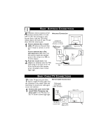
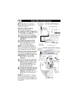
2 CABLE BOX CONNECTIONS If your cable signal uses a cable box or decoder, follow the easy steps below to complete the connection. Cable Signal IN from the Cable Company Cable Box (w/RF In/Outputs): Output Channel Switch Cable Box (w/RF In/Outputs): This connection will be mono. 12 1 Connect the Cable Company supplied cable to the signal IN(put) plug CABLE on the back of the Cable Box. IN TO TV OUTPUT CH 3 4 2 Using a separate round coaxial cable, connect one end to the OUT(put) Jack Panel Back of Cable Box (TO TV) plug on the back of the Cable Box. 3 3 Connect the other end of the round coaxial cable to the 75Ω input on the back of the television. ANT 75‰ Monitor out AV1 in VIDEO Y L/Mono AUDIO Pb AV2 in R Pr COMPONENT VIDEO INPUT S-VIDEO Screw it down finger tight. Round 75Ω NOTE: Set the OUTPUT CHANNEL Coaxial Cable Jack Panel Back of TV SWITCH on the back of the cable box to CH 3 or 4. Tune the TV to the same chan- Cable Signal Cable Box (w/Audio/Video Outputs): nel and change channels at the cable box. IN from the Cable Company Cable Box (w/Audio/Video Outputs): This connection will supply Stereo sound. 4 24 4 Connect the Cable Company supplied cable to the cable signal Cable Box with A/V Outputs OUTPUT CH IN(put) plug on the back of the Cable Box. CABLE IN 3 4 TO TV VIDEO OUT L R AUDIO OUT 5 Using an RCA type Video Cable, con- Video Cable (Yellow) nect one end of the cable to the Video (or ANT, your cable box may be labeled differently) Out jack on the ANT 75‰ 5 Monitor out AV1 in Audio Cables L & R (Red, White) AV2 in cable box and the other end to the VIDEO AV1 Video Input on the TV. Y L/Mono 6 Connect one end of the Audio Left and Right Cable to the left and right Audio Out L & R jacks on the AUDIO Pb R Pr COMPONENT VIDEO INPUT S-VIDEO 6 cable box. Connect the other end to the AV1 Audio L & R Input jacks on Jack Panel Back of TV the TV. NOTE: Use the Channel + or - buttons on the TV remote control to tune to the AV1 channel for the cable box signal. Once ANT 75‰ Monitor out AV1 in VIDEO Y L/Mono AUDIO Pb AV2 in R Pr COMPONENT VIDEO INPUT S-VIDEO tuned, change channels at the cable box, not the television.
-
 1
1 -
 2
2 -
 3
3 -
 4
4 -
 5
5 -
 6
6 -
 7
7 -
 8
8 -
 9
9 -
 10
10 -
 11
11 -
 12
12 -
13
-
14
-
15
-
16
-
17
-
18
-
19
-
20
-
21
-
22
-
23
-
24
-
25
-
26
-
27
-
28
-
29
-
30
-
31
-
32
-
33
-
34
-
35
-
36
 |
 |
