Makita GA5040X1 Makita GA5040X1 Instruction Manual - Page 7
Functional Description, Assembly
 |
View all Makita GA5040X1 manuals
Add to My Manuals
Save this manual to your list of manuals |
Page 7 highlights
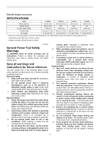
FUNCTIONAL DESCRIPTION ASSEMBLY CAUTION: • Always be sure that the tool is switched off and unplugged before adjusting or checking function on the tool. Shaft lock 1. Shaft lock 1 CAUTION: • Always be sure that the tool is switched off and unplugged before carrying out any work on the tool. Installing side grip (handle) 012725 CAUTION: • Never actuate the shaft lock when the spindle is moving. The tool may be damaged. Press the shaft lock to prevent spindle rotation when installing or removing accessories. Switch action 1 1. Slide switch 012728 CAUTION: • Before plugging in the tool, always check to see that the slide switch actuates properly and returns to the "OFF" position when the rear of the slide switch is depressed. • Switch can be locked in "ON" position for ease of operator comfort during extended use. Apply caution when locking tool in "ON" position and maintain firm grasp on tool. To start the tool, slide the slide switch toward the "I (ON)" position by pushing the rear of the slide switch. For continuous operation, press the front of the slide switch to lock it. To stop the tool, press the rear of the slide switch, then slide it toward the "O (OFF)" position. 012724 CAUTION: • Always be sure that the side grip is installed securely before operation. Screw the side grip securely on the position of the tool as shown in the figure. Installing or removing wheel guard (For depressed center wheel, multi-disc, flex wheel, wire wheel brush / abrasive cut-off wheel, diamond wheel) WARNING: • When using a depressed center wheel, multi-disc, flex wheel or wire wheel brush, the wheel guard must be fitted on the tool so that the closed side of the guard always points toward the operator. • When using an abrasive cut-off / diamond wheel, be sure to use only the special wheel guard designed for use with cut-off wheels. For tool with locking screw type wheel guard 1. Wheel guard 2. Bearing box 3. Screw 1 2 3 012733 Mount the wheel guard with the protrusions on the wheel guard band aligned with the notches on the bearing box. Then rotate the wheel guard around 180 ゚ counterclockwise. Be sure to tighten the screw securely. To remove wheel guard, follow the installation procedure in reverse. 7
-
 1
1 -
 2
2 -
 3
3 -
 4
4 -
 5
5 -
 6
6 -
 7
7 -
 8
8 -
 9
9 -
 10
10 -
 11
11 -
 12
12 -
13
-
14
-
15
-
16
-
17
-
18
-
19
-
20
-
21
-
22
-
23
-
24
-
25
-
26
-
27
-
28
-
29
-
30
-
31
-
32
-
33
-
34
-
35
-
36
-
37
-
38
-
39
-
40
-
41
-
42
-
43
-
44
 |
 |
