Makita GA5040X1 Makita GA5040X1 Instruction Manual - Page 8
Installing or removing depressed center
 |
View all Makita GA5040X1 manuals
Add to My Manuals
Save this manual to your list of manuals |
Page 8 highlights
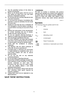
For tool with clamp lever type wheel guard 1 1. Wheel guard 2. Bearing box 3. Screw 4. Lever 2 3 4 009430 Pull the lever in the direction of the arrow after loosening the screw. Mount the wheel guard with the protrusions on the wheel guard band aligned with the notches on the bearing box. Then rotate the wheel guard around 180 ゚. 1 2 1. Screw 2. Lever 1. Lock nut wrench 1 2. Shaft lock 2 012727 To tighten the lock nut, press the shaft lock firmly so that the spindle cannot revolve, then use the lock nut wrench and securely tighten clockwise. To remove the wheel, follow the installation procedure in reverse. Installing or removing flex wheel (optional accessory) WARNING: • Always use supplied guard when flex wheel is on tool. Wheel can shatter during use and guard helps to reduce chances of personal injury. 009431 Tighten the wheel guard with fastening the screw after pulling lever in the direction of the arrow. The setting angle of the wheel guard can be adjusted with the lever. To remove wheel guard, follow the installation procedure in reverse. Installing or removing depressed center wheel or multi-disc (optional accessory) WARNING: • When using a depressed center wheel or multi-disc, the wheel guard must be fitted on the tool so that the closed side of the guard always points toward the operator. 1 1. Lock nut 2. Depressed 2 center wheel 3 3. Inner flange 1 1. Lock nut 2. Flex wheel 2 3. Plastic pad 3 4. Inner flange 4 012740 Follow instructions for depressed center wheel but also use plastic pad over wheel. See order of assembly on accessories page in this manual. Installing or removing abrasive disc (optional accessory) NOTE: • Use sander accessories specified in this manual. These must be purchased separately. 1 1. Sanding lock nut 2 2. Abrasive disc 3. Rubber pad 3 012802 Mount the inner flange onto the spindle. Fit the wheel/disc on the inner flange and screw the lock nut onto the spindle. 012742 Mount the rubber pad onto the spindle. Fit the disc on the rubber pad and screw the sanding lock nut onto the spindle. To tighten the sanding lock nut, press the shaft 8
-
 1
1 -
2
-
 3
3 -
 4
4 -
 5
5 -
 6
6 -
 7
7 -
 8
8 -
 9
9 -
 10
10 -
 11
11 -
 12
12 -
 13
13 -
14
-
15
-
16
-
17
-
18
-
19
-
20
-
21
-
22
-
23
-
24
-
25
-
26
-
27
-
28
-
29
-
30
-
31
-
32
-
33
-
34
-
35
-
36
-
37
-
38
-
39
-
40
-
41
-
42
-
43
-
44
 |
 |
