Makita LS1216L Owners Manual - Page 9
Slide lock adjustment, Switch action - used
 |
View all Makita LS1216L manuals
Add to My Manuals
Save this manual to your list of manuals |
Page 9 highlights
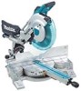
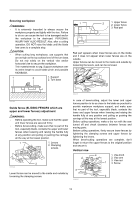
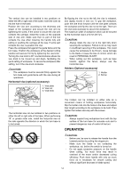
When tilting the carriage to the right, tilt the carriage to the left slightly after loosening the lever and press the releasing button. With the releasing button being pressed, tilt the carriage to the right. 1. Lever 2. Latch lever Slide lock adjustment 1. Lock lever 2. Screw 2 1 009489 1 1. Latch lever 010322 Tilt the saw blade until the pointer points to the desired angle on the bevel scale. Then tighten the lever clockwise firmly to secure the arm. 4 3 1. Scale plate 2. Release button 3. Pointer 4. Latch lever 2 1 009513 When the latch lever is pulled toward yourself, the saw blade can be locked using positive stops at the right and left 22.5 ° and 33.9 ° angle to the base surface. When the latch lever is pushed forward as shown in the figure, the saw blade can be locked at an desired angle within the specified bevel angle range. CAUTION: • When tilting the saw blade, be sure to raise the handle fully. • After changing the bevel angle, always secure the arm by tightening the lever clockwise. • When changing bevel angles, be sure to position the kerf boards appropriately as explained in the "Positioning kerf boards" section. 1 009496 To lock the lower slide pole, pull the lock lever toward yourself. To lock the upper slide pole, turn the locking screw clockwise. Switch action CAUTION: • Before plugging in the tool, always check to see that the switch trigger actuates properly and returns to the "OFF" position when released. • Do not pull the switch trigger hard without pressing in the lock-off button. This can cause switch breakage. 1. Switch trigger 2. Lock-off button 3. Hole for padlock 1 3 2 009491 To prevent the switch trigger from being accidentally pulled, a lock-off button is provided. To start the tool, press in the lock-off button and pull the switch trigger. Release the switch trigger to stop. A hole is provided in the switch trigger for insertion of padlock to lock the tool off. WARNING: • Do not use a lock with a shank or cable any smaller than 6.35 mm (1/4") in diameter. • NEVER use tool without a fully operative switch trigger. Any tool with an inoperative switch is HIGHLY DANGEROUS and must be repaired before further usage. • For your safety, this tool is equipped with a lock-off button which prevents the tool from unintended starting. NEVER use the tool if it runs when you simply pull the switch trigger without pressing the lock-off button. Return tool to a Makita service 9
-
 1
1 -
2
-
3
-
 4
4 -
 5
5 -
 6
6 -
 7
7 -
 8
8 -
 9
9 -
 10
10 -
 11
11 -
 12
12 -
 13
13 -
 14
14 -
15
-
16
-
17
-
18
-
19
-
20
-
21
-
22
-
23
-
24
-
25
-
26
-
27
-
28
-
29
-
30
-
31
-
32
-
33
-
34
-
35
-
36
-
37
-
38
-
39
-
40
-
41
-
42
-
43
-
44
-
45
-
46
-
47
-
48
-
49
-
50
-
51
-
52
-
53
-
54
-
55
-
56
-
57
-
58
-
59
-
60
-
61
-
62
-
63
-
64
-
65
-
66
-
67
-
68
-
69
-
70
-
71
-
72
-
73
-
74
-
75
-
76
-
77
-
78
-
79
-
80
-
81
-
82
-
83
-
84
 |
 |
