Makita LS1221 Owners Manual - Page 25
Bevel angle
 |
View all Makita LS1221 manuals
Add to My Manuals
Save this manual to your list of manuals |
Page 25 highlights
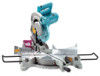
001848 Lower the handle fully and lock it in the lowered position 1 by pushing in the stopper pin. Square the side of the 2 blade with the face of the guide fence using a triangular rule, try-square, etc. Then securely tighten the hex bolts on the guide fence in the order from the right side. 1. Triangular rule 2. Guide fence 3. Grip 3 001836 4 Make sure that the pointer points to 0° on the miter scale. If the pointer does not point to 0°, loosen the screw which secures the pointer and adjust the pointer so that it will point to 0°. 1 2 3 1. Miter scale 2. Pointer 3. Grip 4. Lock lever 001850 1 2 3 1. Lever 2. Turn base 3. 0° bevel angle adjusting bolt 001819 1 2 3 2. Bevel angle (1) 0° bevel angle Lower the handle fully and lock it in the lowered position by pushing in the stopper pin. Loosen the lever at the rear of the tool. Turn the 0° bevel angle adjusting bolt on the left side of the turn base two or three revolutions counterclockwise to tilt the blade to the right. Carefully square the side of the blade with the top surface of the turn base using the triangular rule, try-square, etc. by turning the 0° bevel angle adjusting bolt clockwise. Then tighten the lever securely. 1. Triangular rule 2. Saw blade 3. Top surface of turn base 25
-
 1
1 -
2
-
3
-
4
-
5
-
6
-
7
-
8
-
9
-
10
-
11
-
12
-
13
-
14
-
15
-
16
-
17
-
18
-
19
-
 20
20 -
 21
21 -
 22
22 -
 23
23 -
 24
24 -
 25
25 -
 26
26 -
 27
27 -
 28
28 -
 29
29 -
 30
30 -
31
-
32
 |
 |
