Maytag MEC4436AAC Installation Instructions - Page 2
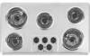
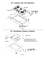
Cooktop with Coil Elements
 |
View all Maytag MEC4436AAC manuals
Add to My Manuals
Save this manual to your list of manuals |
Page 2 highlights
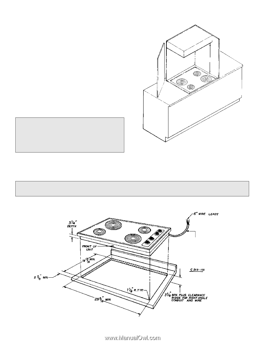
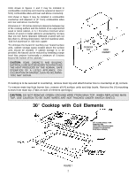
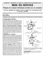
Units shown in figures 1 and 2 may be installed in combustible countertop and must be spaced at least (1² from) combustible sides and rear wall above countertop. Unit shown in figure 3 may be installed in combustible countertop and adjacent to (0² from) combustible sides and rear wall above countertop. Dimension A = 30-inches minimum clearance between top of the cooking surface and the bottom of an unprotected wood or metal cabinet, or A = 24-inches minimum when bottom of wood or metal cabinet is protected by not less than 1/4 inch flame retardant millboard covered with not less than no. 28 msg sheet steel, .015 inch stainless steel, .024 inch aluminum or .020 inch copper. "To eliminate the hazard of reaching over heated surface units, cabinet storage space located above the surface units should be avoided. If cabinet storage is to be provided, the hazard can be reduced by installing a range hood that projects horizontally a minimum of 5-inches beyond the bottom of the cabinets." CAUTION: SOME CABINETS AND BUILDING MATERIALS ARE NOT DESIGNED TO WITHSTAND THE HEAT PRODUCED BY THE NORMAL SAFE OPERATION OF A LISTED APPLIANCE. DISCOLORATION OR DAMAGE, SUCH AS DELAMINATION, MAY OCCUR. "A" COUNTER TOP BASE CABINET If cooktop is to be secured to countertop, remove main top and attach burner box to countertop at (4) corners. To remove main top from burner box, remove all (4) surface units and drip bowls. Remove the (4) mounting screws from main top. (Tabs on side of element openings.) CAUTION: DO NOT REMOVE GREEN GROUND WIRE FROM MAIN TOP. WHEN REPLACING MAIN TOP, USE CAUTION TO BE SURE WIRES ARE NOT PINCHED UNDER SWITCH SHIELD. 30² Cooktop with Coil Elements 3/8² FLEXIBLE CABLE 3′ MIN. FURNISHED AND INSTALLED BY MANUFACTURER (CONNECT TO 240/120-VOLT ELECTRICAL SERVICE.) FIGURE 1 2
-
 1
1 -
 2
2 -
 3
3 -
 4
4 -
 5
5 -
 6
6 -
 7
7 -
 8
8 -
9
 |
 |