Maytag MGR7662WB Installation Guide - Page 14
To Convert Surface Burners Natural Gas to LP Gas, To Convert Oven Bake Burner Natural Gas to LP Gas - rate
 |
UPC - 883049176468
View all Maytag MGR7662WB manuals
Add to My Manuals
Save this manual to your list of manuals |
Page 14 highlights
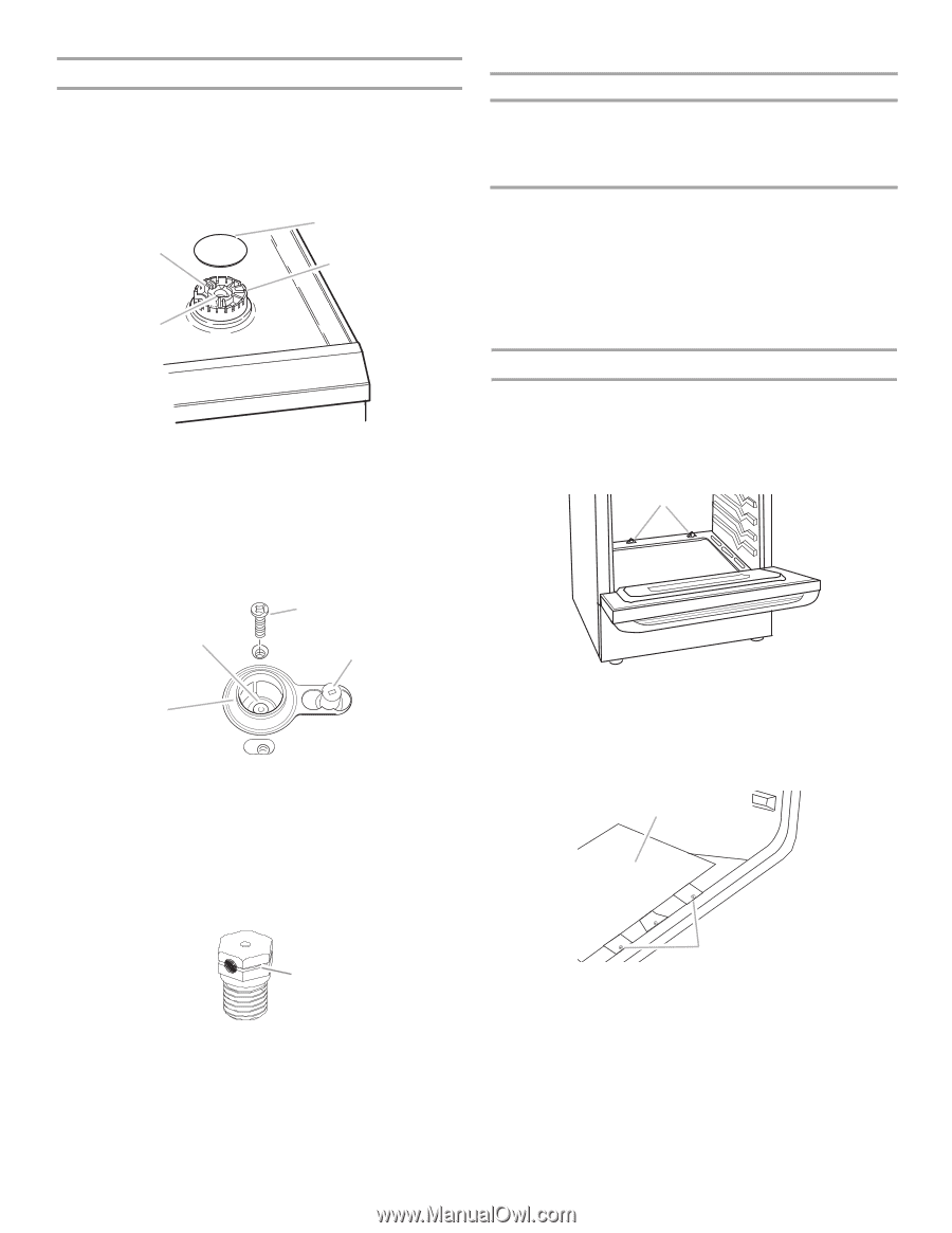
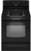
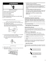
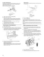
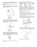
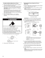
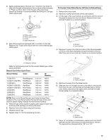
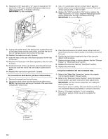
To Convert Surface Burners (Natural Gas to LP Gas) 1. Remove burner cap. 2. Using a Phillips or Quadrex® screwdriver, remove the burner base. NOTE: Reinstall one of the screws through the range cooktop to hold the orifice spud holder in place while removing and replacing the orifice spuds. C A D B A. Igniter electrode B. Gas tube opening C. Burner cap D. Burner base 3. Apply masking tape to the end of a 7 mm nut driver to help hold the gas orifice spud in the nut driver while changing it. Press nut driver down onto the gas orifice spud and remove by turning it counterclockwise and lifting out. Set gas orifice spud aside. C A D B A. Orifice spud B. Orifice spud holder C. Screw D. Spark electrode 4. Remove the cardboard orifice spud holder located on the back of the range near the gas inlet. Gas orifice spuds are stamped with a number, marked with 1 color dot, and have a groove in the hex area. Replace the Natural gas orifice spud with the correct LP gas orifice spud. LP Gas Orifice Spud Chart for Surface Burners Burner Rating Color Size ID Number 14,000 BTU 11,000 BTU 8,000 BTU 5,000 BTU Yellow/Orange Yellow/Brown Yellow/Black Yellow/White 1.07 mm 0.99 mm 0.85 mm 0.70 mm L107 L99 L85 L70 NOTE: Refer to the Model Number and Serial Number Plate located on the oven frame behind the top left side of the oven door for proper sizing of spuds for each burner location. 5. Place Natural gas orifice spuds in the cardboard orifice spud holder. 6. Replace the burner base using both screw. 7. Replace burner cap. 8. Repeat steps 1-7 for the remaining burners. To Convert Oven Bake Burner (Natural Gas to LP Gas) 1. Remove the oven racks. 2. Remove 2 screws at the rear of the oven bottom. 3. Lift the rear of the oven bottom up and back until the front of the panel is away from the front frame. Remove from oven and set it aside on a covered surface. A A. Screws B. Oven bottom 4. Remove 2 screws from the front tabs of the flame spreader. Lift front of the flame spreader and pull forward to remove tabs from rear of oven and set it aside on a covered surface. B A A. LP groove Refer to the following chart for correct LP gas orifice spud placement. A A. Screws B. Flame spreader 5. Remove 2 screws from the bake burner. 14
-
 1
1 -
2
-
3
-
4
-
5
-
6
-
7
-
8
-
 9
9 -
 10
10 -
 11
11 -
 12
12 -
 13
13 -
 14
14 -
 15
15 -
 16
16 -
 17
17 -
 18
18 -
 19
19 -
20
-
21
-
22
-
23
-
24
-
25
-
26
-
27
-
28
-
29
-
30
-
31
-
32
-
33
-
34
-
35
-
36
-
37
-
38
-
39
-
40
 |
 |