Maytag MGR7662WB Installation Guide - Page 8
Make Gas Connection - parts
 |
UPC - 883049176468
View all Maytag MGR7662WB manuals
Add to My Manuals
Save this manual to your list of manuals |
Page 8 highlights
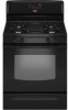
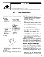
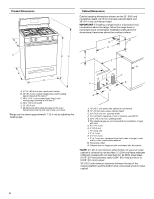
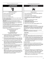
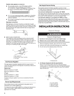
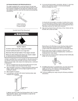
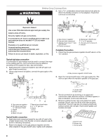
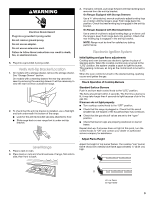
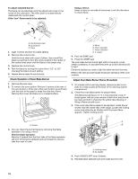
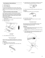
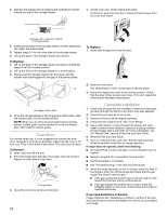
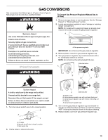
WARNING Make Gas Connection 3. Use a combination wrench and channel lock pliers to attach the flexible connector to the adapters. Check that connector is not kinked. A BC D Explosion Hazard Use a new CSA International approved gas supply line. Install a shut-off valve. Securely tighten all gas connections. If connected to LP, have a qualified person make sure gas pressure does not exceed 14" (36 cm) water column. Examples of a qualified person include: licensed heating personnel, authorized gas company personnel, and authorized service personnel. Failure to do so can result in death, explosion, or fire. E A. Gas pressure regulator B. Use pipe-joint compound. C. Adapter (must have ½" male pipe thread) D. Flexible connector HG F E. Manual gas shutoff valve F. ½" or ¾" gas pipe G. Use pipe-joint compound. H. Adapter Complete Connection 1. Check that the gas pressure regulator shutoff valve is in the "on" position. Typical rigid pipe connection A combination of pipe fittings must be used to connect the range to the existing gas line. Your connections may be different, according to the supply line type, size and location. 1. Apply pipe-joint compound made for use with LP gas to all pipe thread connections. 2. Using a pipe wrench to tighten, connect the gas supply to the range. B C A D F E J A. Gas pressure regulator B. 90° elbow (must have ½" male pipe thread) C. Nipple D. Union E. Black iron pipe I HG F. Manual gas shutoff valve G. ½" or ¾" gas pipe H. Nipple I. Union J. 90° elbow Typical flexible connection 1. Apply pipe-joint compound made for use with LP gas to the smaller thread ends of the flexible connector adapters (see B and G in following illustration). 2. Attach one adapter to the gas pressure regulator and the other adapter to the gas shutoff valve. Tighten both adapters. A A. Gas pressure regulator shutoff valve 2. Open the manual shutoff valve in the gas supply line. The valve is open when the handle is parallel to the gas pipe. A B A. Closed valve B. Open valve 3. Test all connections by brushing on an approved noncorrosive leak-detection solution. If bubbles appear, a leak is indicated. Correct any leak found. 4. Remove cooktop burner caps and grates from parts package. Burner caps should be level when properly positioned. If burner caps are not properly positioned, surface burners will not light. Place burner grates over burners and caps. B A C A. Burner base B. Burner cap C. Burner grate 8
-
 1
1 -
2
-
 3
3 -
 4
4 -
 5
5 -
 6
6 -
 7
7 -
 8
8 -
 9
9 -
 10
10 -
 11
11 -
 12
12 -
 13
13 -
14
-
15
-
16
-
17
-
18
-
19
-
20
-
21
-
22
-
23
-
24
-
25
-
26
-
27
-
28
-
29
-
30
-
31
-
32
-
33
-
34
-
35
-
36
-
37
-
38
-
39
-
40
 |
 |