Maytag MGT3800TW Installation Instructions
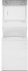
Maytag MGT3800TW - 27" Gas Laundry Center Manual
 |
UPC - 883049046822
View all Maytag MGT3800TW manuals
Add to My Manuals
Save this manual to your list of manuals |
Maytag MGT3800TW manual content summary:
- Maytag MGT3800TW | Installation Instructions - Page 1
27" (69 CM) Table of Contents / Table des mati_res WASHER/DRYER SAFETY ...I S_:CURIT¢: DE LA LAVEUSE/S_:CHEUSE INSTRUCTIONS D'INSTALLATION Outillage et pi_ces ...Autres pi_ces ...Exigences d'emplacement ...13 15 15 15 iNSTALLATiON iNSTRUCTiONS ...3 Tools and Parts ...3 Alternate Parts ...Location - Maytag MGT3800TW | Installation Instructions - Page 2
be performed by a qualified installer. instructions and local codes. - Install the clothes dryer according to the manufacturer's - Do not install a clothes dryer with flexible plastic venting materials, if flexible metal (foil type) duct is installed, it must be of a specific type identified by - Maytag MGT3800TW | Installation Instructions - Page 3
for purchase from the dealer from whom you purchased your dryer. For further information, please reference the "Assistance or Service" section of the Washer/Dryer User Instructions. [] Mobile Home Installation Kit. Ask for Part Number 346764. [] Metal exhaust system hardware. You will need - Maytag MGT3800TW | Installation Instructions - Page 4
Parts" section for information on ordering. Special provisions must be made in mobile homes to introduce outside air into the dryer. The opening (such as a nearby window) should be at least twice as large as the dryer exhaust opening. Washer/Dryer Dimensions 71%" (1819 mm) *Most installations - Maytag MGT3800TW | Installation Instructions - Page 5
or service representative or personnel if you are in doubt as to whether the washer/dryer is properly grounded. Do not modify the plug provided with the washer/dryer: if it wilt not fit the outlet, have a proper outlet installed by a qualified electrician. WARNING: C D SAVE THESE INSTRUCTIONS - Maytag MGT3800TW | Installation Instructions - Page 6
include a shutoff valve: in the U.S.A.: An individual manual shutoff valve must be installed within six (6) feet (1.8 m) of the dryer in accordance with the National Fuel Gas Code, ANSI Z223.1. in Canada: An individual manual shutoff valve must be installed in accordance with the B149.1, Natural Gas - Maytag MGT3800TW | Installation Instructions - Page 7
DURASAFE TM vent products can be purchased from your dealer or by calling Whirlpool Parts and Accessories. For more information, see the "Assistance or Service" section of the Washer/Dryer User Instructions. Rigid metal vent [] For best drying performance, rigid metal vents are recommended. [] Rigid - Maytag MGT3800TW | Installation Instructions - Page 8
until hose contacts the ribbed stops on the cabinet. install the front leveling feet 1. Prop up the front of the washer/dryer about 4" (102 mm) with a wood block or similar object. The block needs to support the weight of the washer/dryer. 2. Screw the Iocknut onto each foot to within 1" (25 - Maytag MGT3800TW | Installation Instructions - Page 9
hoses. Replace access panel upon completion of washer/dryer installation. NOTE: Do not overtighten or use tape washer/dryer. Locate the remaining piece of shipping strap. See "Remove Shipping Strap." Shipping strap A. Cold water inlet valve (top) B. Hot water inlet valve (bottom) 3= In Canada - Maytag MGT3800TW | Installation Instructions - Page 10
are available for purchase. Please reference the "Assistance or C ...ii!:"1H Service" section of the Washer/Dryer User Instructions. [] Over-the-Top Installation: Part Number 4396028 A. Dryer B. Rigid metal or flexible metal vent C. Clamps D. Wall E. Elbow F. Clamps G. Elbow H. Exhaust hood - Maytag MGT3800TW | Installation Instructions - Page 11
combinations acceptable to use. NOTE: Do not use vent runs longer than those specified in the Vent system chart. Exhaust systems longer than those specified will: [] [] Shorten the life of the dryer. Reduce performance, resulting in longer drying times and increased energy usage. 3= If the washer - Maytag MGT3800TW | Installation Instructions - Page 12
are now installed. If there is an extra part, go back through the steps to see which step was skipped. Check that you have all of your tools. Dispose of/recycle all packaging materials. Keep the plastic foam for use if the washer/dryer should be transported. Check the washer/dryer's final location - Maytag MGT3800TW | Installation Instructions - Page 13
potentiel et vous disent comment r6duire le risque de blessure et ce qui peut se produire en cas de non-respect des instructions. AVERTISSEMENT - L'installation - installer de la s_cheuse - "Risque d'incendie" par un installateur du fabricant qualifi_. Iocaux. & linge dolt _tre effectu_e aux - Maytag MGT3800TW | Installation Instructions - Page 14
de la piece, de I'edifice le fournisseur = Appeler immediatement instructions. = A defaut de joindre de gaz d'un telephone de gaz, appeler votre fournisseur les pompiers. qualifie, une - L'installation et l'entretien doivent agence de service ou le fournisseur _tre effectues de gaz. par un - Maytag MGT3800TW | Installation Instructions - Page 15
chez qui vous avez achet6 votre s6cheuse. Pour plus d'informations, consulter la section "Assistance ou service" des Instructions d'utilisation de la laveuse/s6cheuse. [] [] Trousse d'installation pour maison mobile. Demander le num6ro de piece 346764. Syst_me d'6vacuation en m6tal. [] Le non - Maytag MGT3800TW | Installation Instructions - Page 16
". Un plancher robuste pour supporter le poids de la laveuse installation dans un encastrement ou darts un placard On recommande les dimensions Instructions Home Construction and Safety, Titre 24 HUD, partie 280) ou de la Norme CAN/CSA-Z240MH. L'installation 27" (686 ram) *La plupart des installations - Maytag MGT3800TW | Installation Instructions - Page 17
buanderie, ou le systeme de vidange au plancher. Choisissez la m6thode d'installation du tuyau de vidange dont vous avez besoin. Voir "Autres pieces". utiliser un adaptateur. un c_ble de rallonge. Le non-respect de ces instructions peut causer un deces, un Jncendie ou un choc electrique. L'appareil - Maytag MGT3800TW | Installation Instructions - Page 18
une canalisation neuve d'arrivee de gaz approuv_e par CSA International. Installer un robinet d'arr_t. Bien setter chaque organe de connexion de composer les num6ros de t_l_phone indiqu_s sur la page de couverture des instructions d'utilisation de la laveuse/s_cheuse. Conversion au gaz de p_trole - Maytag MGT3800TW | Installation Instructions - Page 19
de r6duire la capacit_ d'_vacuation et le rendement. Ne pas installer le conduit m_tallique flexible dans les cavit_s ferm_es des murs, appelant le service Pieces et accessoires de Whirlpool. Pour plus d'information, voir la section "Assistance ou service" des Instructions pour I'utilisateur - Maytag MGT3800TW | Installation Instructions - Page 20
supporter le poids de la laveuse/s6cheuse. 2. Visser le contre-6crou sur chaque pied a.1" (25 mm) de la base. 1 fl [] Problemes de nettoyage dans la maison et problemes ou fuie, I'installer en suivant les instructions ci-dessous. iMPORTANT : Pour une installation correcte, suivre attentivement - Maytag MGT3800TW | Installation Instructions - Page 21
du ruban adh6sif ou du calfeutrant sur la valve. Les valves risquent d'etre endommag6es. Pour utilisation avec vidange par le plancher Ne pas installer la bride de retenue pour tuyau de vidange sur le tuyau de vidange ondul6. Vous pouvez avoir besoin de pieces suppl6mentaires. Voir Egout au - Maytag MGT3800TW | Installation Instructions - Page 22
Pour recouvrir le trou sur le c6t_, on peut ajouter I'un des bouchons suivants : 692790 (blanc) 3977784 (biscuit) Suivre les instructions dans la trousse d'installation. Les trousses sont disponibles au magasin o_ la laveuse/s_cheuse a _t_ achet_e. i[ A B C B C Si les robinets d'eau et le tuyau - Maytag MGT3800TW | Installation Instructions - Page 23
installations oQ le d6gagement est r6duit. Consulter la section "Assistance ou service" des Instructions pour I'utilisateur de la laveuse/s6cheuse. [] Installation 29" (737 mm) & 50" (1,27 m) de de de Dispositions sp_ciales pour les installations dans une maison mobile Le syst_me d'6vacuation - Maytag MGT3800TW | Installation Instructions - Page 24
ne se met pas de niveau, v6rifier nouveau que les pieds de nivellement arriere peuvent bouger librement tel que d_crit dans la section "Installation des pieds de nivellement". R_p_ter cette 6tape jusqu'& I'aplomb parfait de la laveuse/s_cheuse. REMARQUE : II peut _tre n_cessaire de r_gler encore le - Maytag MGT3800TW | Installation Instructions - Page 25
dans la laveuse. Rabattre le couvercle. S61ectionner HEAVY DUTY (service intense) et tirer sur le bouton de commande des programmes. adaptateur. Ne pas utilJser un cable de rallonge. Le non-respect de ces instructions peut causer un deces, un Jncendie ou un choc electrique. 6. Brancher sur une - Maytag MGT3800TW | Installation Instructions - Page 26
. Tous droits reserv6s. Benton Harbor, Michigan 49022 TM DURASAFE is a trademark of Whirlpool, U.S.A., Whirlpool Canada LP licensee in Canada TM DURASAFE est une marque de commerce de Whirlpool, U.S.A., Emploi licencie par Whirlpool Canada LP au Canada 10/08 Printed in U.S.A. Imprime aux E.-U.
-
 1
1 -
 2
2 -
 3
3 -
 4
4 -
 5
5 -
 6
6 -
 7
7 -
8
-
9
-
10
-
11
-
12
-
13
-
14
-
15
-
16
-
17
-
18
-
19
-
20
-
21
-
22
-
23
-
24
-
25
-
26
 |
 |

27" (69CM)GASWASHER/DRYER
INSTALLATION
INSTRUCTIONS
INSTRUCTIONS
I)'INSTALIATION-
LA USE!SECHEUSE
A GAZ
DE 27"(69 CM)
Table of Contents
/
Table des mati_res
WASHER/DRYER
SAFETY
.............................
I
iNSTALLATiON
iNSTRUCTiONS
...................
3
Tools and Parts
.............................................
3
Alternate
Parts
...............................................
3
Location
Requirements
................................
3
Drain System
.................................................
4
Electrical
Requirements
................................
5
Gas Supply
Requirements
............................
5
Venting
Requirements
...................................
6
Remove
Shipping
Strap
................................
7
Install
Leveling
Legs
......................................
8
Connect
the Drain Hose
................................
8
Connect
the Inlet Hoses
...............................
8
Secure the Drain Hose
..................................
9
Plan Vent System
........................................
10
Install Vent System
......................................
11
Level Washer/Dryer
.....................................
11
Make Gas Connection
................................
11
Connect
Vent
..............................................
12
Complete
Installation
..................................
12
S_:CURIT¢:
DE
LA LAVEUSE/S_:CHEUSE
... 13
INSTRUCTIONS
D'INSTALLATION
..............
15
Outillage
et pi_ces
.......................................
15
Autres
pi_ces
..............................................
15
Exigences
d'emplacement
........................
15
Syst_me
de vidange
...................................
17
Specifications
_lectriques
...........................
17
Specifications
de I'alimentation
en gaz
......
18
Exigences
concernant
I'_vacuation
............
19
Enlever la sangle d'exp_dition
....................
20
Installation
des
pieds de nivellement
..........
20
Raccordement
du tuyau de vidange
..........
20
Raccordement
des tuyaux
d'alimentation..
21
Immobilisation
du tuyau de vidange
...........
22
Planification
du syst_me
d'_vacuation
.......
22
Installation
du syst_me
d'_vacuation
.........
24
Nivellement
de la laveuse/s_cheuse
...........
24
Raccordement
h la canalisation
de gaz
......
24
Raccordement
du conduit
d'_vacuation
.....
25
Achever
I'installation
...................................
25
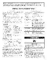
WASHER RYER SAFETY
Your
safety
and
the
safety
of others
are
very
important.
We
have
provided
many
important
safety
messages
in this
manual
and
on your
appliance.
Always
read
and
obey
all safety
messages.
This is the safety alert symbol.
This symbol
alerts you to potential
hazards
that can kilt or hurt you and others.
All safety messages
will follow the safety
alert symbol
and either the word "DANGER"
or "WARNING."
These
words mean:
You
can
be killed
or seriously
injured
if
you
don't
immediately
follow
instructions.
You
can
be killed
or
seriously
injured
if
you
don't
follow
instructions.
All safety messages
wilt tell you what the potential
hazard
is, tell you how to reduce the chance
of injury, and tell you what can
happen
if the instructions
are not followed.
W10222381A