Maytag MMV1175 Installation Instructions
Maytag MMV1175 Manual
 |
View all Maytag MMV1175 manuals
Add to My Manuals
Save this manual to your list of manuals |
Maytag MMV1175 manual content summary:
- Maytag MMV1175 | Installation Instructions - Page 1
electric or gas cooking products up to and including 36" (91.4 cm) wide. See the "Installation Requirements" section for further notes. These installation instructions cover different models. The appearance of your particular model may differ slightly from the illustration in these installation - Maytag MMV1175 | Installation Instructions - Page 2
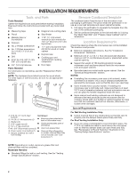
filters may roof venting) not be included. See "User Instructions.") Remove Cardboard Template The cardboard piece from the top of minimum 3/8" (1 cm) thickness drywall or plaster/lath within cabinet opening. ■ Support for weight of 150 lbs (68 kg) which includes microwave oven and items - Maytag MMV1175 | Installation Instructions - Page 3
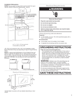
a grounded 3 prong outlet. Do not remove ground prong. Do not use an adapter. Do not use an extension cord. Failure to follow these instructions can result in death, fire, or electrical shock. A. 2" x 4" (5.1 x 10.2 cm) wall stud B. Grounded 3 prong outlet *30" (76.2 cm) is typical for 66" (167 - Maytag MMV1175 | Installation Instructions - Page 4
INSTALLATION INSTRUCTIONS Remove Mounting Plate Depending on your model, the mounting plate may be in the foam packaging, or it may be attached to the back of - Maytag MMV1175 | Installation Instructions - Page 5
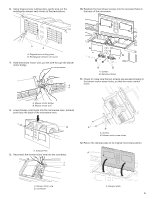
6. Using diagonal wire cutting pliers, gently snip out the rectangular damper vent covers at the perforations. 10. Reattach the two blower screws into the recessed holes in the back of the microwave. A B A. Diagonal wire cutting pliers B. Rectangular damper vent cover 7. Hold the blower motor wire - Maytag MMV1175 | Installation Instructions - Page 6
13. Secure damper plate with two screws removed in Step 1. A B A. Damper plate B. Screws Roof Venting Installation Only 1. Repeat Step 1 from "Wall Venting Installation Only." 2. Repeat Step 2 from "Wall Venting Installation Only." 3. Repeat Step 3 from "Wall Venting Installation Only." 4. Repeat - Maytag MMV1175 | Installation Instructions - Page 7
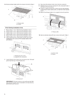
C C F F A. End holes (on mounting plate) B. Cabinet opening vertical centerline C. Wall stud centerlines D. Holes for lag screws E. Support tabs F. Mounting plate center markers Mark Rear Wall The microwave oven must be installed on a minimum of one wall stud, preferably two, using a minimum - Maytag MMV1175 | Installation Instructions - Page 8
the upper cabinet and must be on a level line with each other. They must each be 141⁄8" (35.96 cm) from the centerline. 5. With the support tabs facing forward (see illustrations in the "Locate Wall Stud(s)" section), align the mounting plate center markers to the centerline on the wall, making sure - Maytag MMV1175 | Installation Instructions - Page 9
alignment of mounting plate, making sure it is level. 7. Securely tighten all lag screws and bolts. Wall Stud at One End Hole (Figure 3) 1. With the support tabs of the mounting plate facing forward, insert a 3/16-24 x 3" round-head bolt through the end hole that fits over the 5/8" (16 mm) hole - Maytag MMV1175 | Installation Instructions - Page 10
shut. 4. Using two or more people, lift microwave oven and hang it on support tabs at the bottom of mounting plate. NOTE: To avoid damage to the near the 3/8" (10 mm) holes. 10 A B A. Mounting plate B. Support tabs 5. With front of microwave oven still tilted, thread power supply cord through - Maytag MMV1175 | Installation Instructions - Page 11
not tripped. Replace the fuse or reset the circuit breaker. If the problem continues, call an electrician. ■ Check that the power supply cord is plugged into a grounded 3 prong outlet. ■ See the User Instructions for troubleshooting information. The installation is now complete. Save Installation - Maytag MMV1175 | Installation Instructions - Page 12
VENTING DESIGN SPECIFICATIONS This section is intended for architectural designer and builder/ contractor reference only. NOTES: ■ Vent materials needed for installation are not provided with microwave hood combination. ■ We do not recommend using a flexible metal vent. ■ To avoid possible product - Maytag MMV1175 | Installation Instructions - Page 13
Recommended Vent Length A 31⁄4" x 10" (8.3 x 25.4 cm) rectangular or 6" (15.2 cm) round vent should be used. The total length of the vent system including straight vent, elbow(s), transitions and wall or roof caps must not exceed the equivalent of 140 ft (42.7 m) for either type of vent. See the " - Maytag MMV1175 | Installation Instructions - Page 14
ASSISTANCE Call your authorized dealer or service center. When you call, you will need the the installation hardware needs to be replaced, call us at our toll-free number listed in the User Guide. Following is a list of available replacement parts. You will need your model and serial numbers located - Maytag MMV1175 | Installation Instructions - Page 15
Notes 15 - Maytag MMV1175 | Installation Instructions - Page 16
W11485889B SP PN W11485890 ©2020 All rights reserved. 10/20
-
 1
1 -
 2
2 -
 3
3 -
 4
4 -
 5
5 -
 6
6 -
 7
7 -
8
-
9
-
10
-
11
-
12
-
13
-
14
-
15
-
16
 |
 |
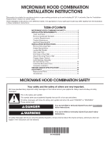
MICROWAVE HOOD COMBINATION
INSTALLATION INSTRUCTIONS
This product is suitable for use above electric or gas cooking products up to and including 36" (91.4 cm) wide. See the “Installation
Requirements” section for further notes.
These installation instructions cover different models. The appearance of your particular model may differ slightly from the illustration
in these installation instructions.
Table of Contents
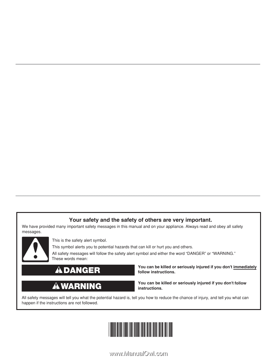
MICROWAVE HOOD COMBINATION SAFETY
W11485889B
MICROWAVE HOOD COMBINATION SAFETY
............................
1
INSTALLATION REQUIREMENTS
.................................................
2
Tools
and Parts
............................................................................
2
Remove Cardboard Template
......................................................
2
Location Requirements
................................................................
2
Product Dimensions
.....................................................................
3
Electrical Requirements
...............................................................
3
INSTALLATION INSTRUCTIONS
...................................................
4
Remove Mounting Plate
...............................................................
4
Rotate Blower Motor
....................................................................
4
Locate Wall Stud(s)
......................................................................
7
Mark Rear Wall
.............................................................................
7
Drill Holes in Rear Wall
.................................................................
8
Attach Mounting Plate to Wall
.....................................................
8
Prepare Upper Cabinet
................................................................
9
Install Damper Assembly
(for wall venting only)
..................................................................
10
Install the Microwave Oven
........................................................
10
Complete Installation
.................................................................
11
VENTING DESIGN SPECIFICATIONS
........................................
12
ASSISTANCE
................................................................................
14
Replacement Parts
.....................................................................
14
Accessories
................................................................................
14