McAfee IIP-M80K-ISAA Quick Start Guide - Page 2
STEP 2: Add the sensor to your Manager - pc
 |
View all McAfee IIP-M80K-ISAA manuals
Add to My Manuals
Save this manual to your list of manuals |
Page 2 highlights
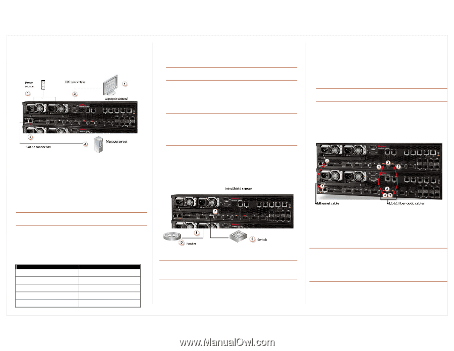
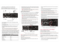
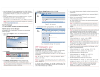
6. Repeat Steps 1 through 5 for the secondary sensor. Cable the Management and Console ports Make sure the sensor is powered OFF before attaching cables. Figure 8: Sensor setup 1. Plug a Category 5e Ethernet cable in the (Management) Mgmt port of M-8000 P. 2. Plug the other end of the cable into the network device connected to your Manager server. 3. Plug the DB9 Console cable supplied in the sensor box into the Console port (labeled Console on the sensor front panel) of M-8000 P. Note: You can use the Console port on the secondary sensor, M-8000 S, for a flash recovery process or to troubleshoot. 4. Connect the other end of the Console port cable directly to a COM port of the PC or terminal server you will be using to configure the sensor (for example, a PC running correctly configured Windows Hyperterminal software). You must connect directly to the console for initial configuration; you cannot configure the sensor remotely. The required settings for Hyperterminal are: Name Setting Baud rate 38400 Number of Bits 8 Parity None Stop Bits 1 Control Flow None 5. Plug the female end of a power cable into the power inlet and plug the other end into a power source. The sensor ships with standard US power and international cables. Note: The M-8000 does not have a power switch; you need only plug the power cable into a power source. Cable the Monitoring ports This procedure describes how to cable a sensor to run in in-line mode. 1. Plug the cable appropriate for use with your XFP or SFP module into one of the Monitoring ports labeled xA (for example, 1A). Note: McAfee supports only those SFP/XFP modules purchased through McAfee or from a McAfee-approved vendor. Note: Do not use XC ports. These ports are reserved for interconnection between the primary (M-8000 P) and secondary (M-8000 S) sensors. 2. Plug another cable into the peer of the port used in Step 1. This port will be labeled xB (for example, 1B). 3. Connect the other end of each cable to the network devices that you want to monitor. (For example, if you plan to monitor traffic between a switch and a router, connect the cable connected to 1A to the router and the one connected to 1B to the switch.) Figure 9: Cable sensor for in-line mode Note: For instructions on how to cable the sensor to run in other operating modes, see the IntruShield Sensor Product Guide for your sensor model. Cable the interconnect ports This procedure describes how to connect the primary sensor to the secondary sensor. 1. Plug the supplied Ethernet cable into the XC1 port of the primary sensor. 2. Connect the other end of the Ethernet cable used in Step 1 into the XC4 port of the secondary sensor. 3. Insert the supplied XFP modules into the XC2, XC3, XC5, and XC6 ports on the primary and secondary sensors. Note: McAfee supports only those XFP modules purchased through McAfee or from a McAfee-approved vendor. 4. Plug one end of an LC-LC fiber-optic cable into the XC2 port of the primary sensor and connect the other the cable to the XC5 port of the secondary sensor. 5. Plug one end of an LC-LC fiber-optic cable into the XC3 port of the primary sensor and connect the other the cable to the XC6 port of the secondary sensor. Figure 10: Cable primary sensor to secondary sensor STEP 2: Add the sensor to your Manager Install the Manager software For detailed instructions, refer to the Manager Installation Guide. Note: You must have Administrator privileges on the target Windows server to install the Manager software. A MySQL database is included with the Manager and is installed (embedded) automatically on your target Windows server during this process. 1. Prepare the system according to the requirements outlined in the Manager Installation Guide and the IntruShield Release Notes. 2. Close all open applications.
-
 1
1 -
 2
2 -
 3
3 -
 4
4
 |
 |