Motorola 549478-001-00 User Guide - Page 12
System Description
 |
UPC - 766796451012
View all Motorola 549478-001-00 manuals
Add to My Manuals
Save this manual to your list of manuals |
Page 12 highlights
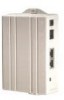
System Description System Description The T3 PowerBroadband system is designed primarily for hospitality, but useful in any high density MDU (multiple dwelling unit) such as long term healthcare or centrally wired apartments. The system is comprised of two primary components; a 25-port Switch and a CPE device (the WallPlate). Advanced networking features such as 802.1Q VLANs and QoS can be managed throughout the system, from the 25-port switch to each port on the WallPlate. Adaptive Line Power T3 PowerBroadband delivers operating power to the remote WallPlates. MC-802 Wireless WallPlate M2 Ethernet WallPlate Line powered up to 300m (1000ft) Line powered up to 600m (2000ft) T3 PowerBroadband Switch The T3 switch is installed in a centrally located phone room; where all the telephone wires converge. The T3 switch has 25 ports for downstream WallPlates, and 2 x GigE uplink ports. T3 PowerBroadband Switch: Physical • 17.50"(43.8mm) x 14.25" (36mm) x 1.75" (44mm). 11.5lbs (5.2Kg) • Operating Temperature: 0 - 50 degrees Celsius, 5% to 90% NC • Operating Power: 300W maximum under full load, 200W typical Interfaces • Uplink ports o Two 10/100/1000Mb autosensing, full duplex Ethernet ports via RJ45 • Downlink ports o 25 VDSL UTP ports via RJ21 telco connector Layer-2 Networking Features • 802.1Q VLAN trunk ports • 802.1Q PVID per port • Port-based Isolation VLANs • QoS, 4 queues per port, classification by IP-TOS or L2-COS bit • IGMP, Layer 2+ routing, proxy, FastLeave • 1024 entry MAC forwarding table Management • Telnet, Console, webUI, Syslog, SNMPv2c • RADIUS authentication, Admin and User level login • Security: L2 VLAN, IP ACL M2 Ethernet WallPlate The m2 Ethernet WallPlate has two 10/100Mb Ethernet ports, and a pass-through RJ11 phone connector. It is installed at the end-point where Ethernet service is desired. It operates over a standard 2-wire telephone line. Motorola, Inc. 570510-001-00 rev A Page 12 of 50
-
 1
1 -
2
-
3
-
4
-
5
-
6
-
 7
7 -
 8
8 -
 9
9 -
 10
10 -
 11
11 -
 12
12 -
 13
13 -
 14
14 -
 15
15 -
 16
16 -
 17
17 -
18
-
19
-
20
-
21
-
22
-
23
-
24
-
25
-
26
-
27
-
28
-
29
-
30
-
31
-
32
-
33
-
34
-
35
-
36
-
37
-
38
-
39
-
40
-
41
-
42
-
43
-
44
-
45
-
46
-
47
-
48
-
49
-
50
 |
 |
