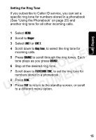
Motorola MD7091 User Guide - Page 31
Tel Line 1/ L1 + L2, Tel Line 2, jacks designated for Line 1 and Line 2.
 |
UPC - 612572121726
View all Motorola MD7091 manuals
Add to My Manuals
Save this manual to your list of manuals |
Page 31 highlights
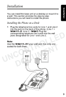
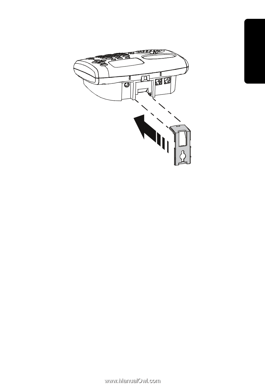
Installation 3 Turn the wall mount over so the key slot is facing upward. Align the wall mount with grooves on the base and push gently until the mount clicks in place. LLED 4 Plug the power cord into the back of the base and into an electrical outlet. NTRO 5 Plug the telephone line cords for Line 1 and Line 2 UNCO ENT into the jack on the back of the phone. (Line 1 = Tel Line 1/ L1 + L2. Line 2 = Tel Line 2) Plug the corresponding telephone line cords into the wall DOCUM jacks designated for Line 1 and Line 2. 11
-
 1
1 -
2
-
3
-
4
-
5
-
6
-
7
-
8
-
9
-
10
-
11
-
12
-
13
-
14
-
15
-
16
-
17
-
18
-
19
-
20
-
21
-
22
-
23
-
24
-
25
-
 26
26 -
 27
27 -
 28
28 -
 29
29 -
 30
30 -
 31
31 -
 32
32 -
 33
33 -
 34
34 -
 35
35 -
 36
36 -
37
-
38
-
39
-
40
-
41
-
42
-
43
-
44
-
45
-
46
-
47
-
48
-
49
-
50
-
51
-
52
-
53
-
54
-
55
-
56
-
57
-
58
-
59
-
60
-
61
-
62
-
63
-
64
-
65
-
66
-
67
-
68
-
69
-
70
-
71
-
72
 |
 |
11
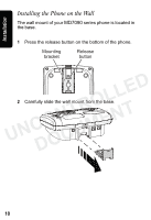
Installation
3
Turn the wall mount over so the key slot is facing
upward. Align the wall mount with grooves on the base
and push gently until the mount clicks in place.
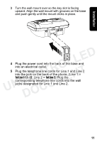
4
Plug the power cord into the back of the base and
into an electrical outlet.
5
Plug the telephone line cords for Line 1 and Line 2
into the jack on the back of the phone. (Line 1 =
Tel Line 1/ L1 + L2
.
Line 2 =
Tel Line 2
) Plug the
corresponding telephone line cords into the wall
jacks designated for Line 1 and Line 2.
UNCONTROLLED
DOCUMENT