NEC AS193i-BK Users Manual - Page 8
Remove Monitor Stand for Mounting, B.1 - ts
 |
View all NEC AS193i-BK manuals
Add to My Manuals
Save this manual to your list of manuals |
Page 8 highlights
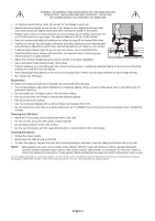
3. Connect the 15-pin mini D-SUB of the video signal cable to the appropriate connector on the back of the monitor (Figure B.1). 4. Connect one end of the power cord to the monitor and the other end to the power outlet. Place the Video Signal Cable and power cord to the Cable holder (Figure C.1). NOTE: Adjust position of cable placed to the Cable holder to avoid damage for cable or monitor. NOTE: Please refer to Caution section of this manual for proper selection of power cord. 5. Turn on the monitor with the bottom power button and the computer (Figure D.1). Power cable Input (VGA) Input (DVI) Figure B.1 Figure C.1 Figure D.1 Power Button 6. No-touch Auto Adjust automatically adjusts the monitor to optimal settings upon initial setup for most timings. For further adjustments, use the following OSD controls: • Auto Adjust Contrast • Auto Adjust Refer to the Controls section of this User's Manual for a full description of these OSD controls. NOTE: If you have any problem, please refer to the Troubleshooting section of this User's Manual. Tilt Grasp both sides of the monitor screen with your hands and adjust the tilt as desired (Figure TS.1). Remove Monitor Stand for Mounting To prepare the monitor for alternative mounting purposes: 1. Disconnect all cables. Figure TS.1 2. Place monitor face down on a non-abrasive surface (Figure R.1). 3. Remove the 4 screws connecting the monitor to the stand and remove the stand as indicated (Figure R.2). The monitor is now ready for mounting in an alternative manner. 4. Connect the AC cord and signal cable to the back of the monitor (Figure R.3). 5. Reverse this process to re-attach stand. NOTE: Use only VESA-compatible alternative mounting method. NOTE: Handle with care when removing monitor stand. English-6
-
 1
1 -
2
-
 3
3 -
 4
4 -
 5
5 -
 6
6 -
 7
7 -
 8
8 -
 9
9 -
 10
10 -
 11
11 -
 12
12 -
 13
13 -
14
-
15
-
16
-
17
-
18
 |
 |
