Netgear CSM4532 Hardware Installation Guide - Page 16
AC Power Connector with Plug
 |
View all Netgear CSM4532 manuals
Add to My Manuals
Save this manual to your list of manuals |
Page 16 highlights
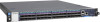
Rear view of the switch Model M4500-32C No. Item 1 AC Power Connector (with Plug Retainer) 2 Earth Grounding (M4 screw) 3 PSU Warning LED 4 PSU DC LED 5 PSU AC LED No. 6 PSU2 Item 7 Hot-swappable Fan Modules (6) 8 Fan LEDs 9 PSU1 On the rear panel, the left power supply is PSU2 and the right power supply is PSU1. The fan modules from the left to the right are FAN6, FAN5, FAN4, FAN3, FAN2, and FAN1. NETGEAR M4500 Series Switches Hardware Installation Guide 16
-
 1
1 -
2
-
3
-
4
-
5
-
6
-
7
-
8
-
9
-
10
-
 11
11 -
 12
12 -
 13
13 -
 14
14 -
 15
15 -
 16
16 -
 17
17 -
 18
18 -
 19
19 -
 20
20 -
 21
21 -
22
-
23
-
24
-
25
-
26
-
27
-
28
-
29
-
30
-
31
-
32
-
33
 |
 |

Model M4500-32C
NETGEAR M4500 Series Switches Hardware Installation Guide
16
Rear view of the switch
No.
Item
No.
Item
1
AC Power Connector (with Plug
Retainer)
6
PSU2
2
Earth Grounding (M4 screw)
7
Hot-swappable Fan Modules (6)
3
PSU Warning LED
8
Fan LEDs
4
PSU DC LED
9
PSU1
5
PSU AC LED
On the rear panel, the left power supply is PSU2 and the right power supply is PSU1. The fan
modules from the left to the right are FAN6, FAN5, FAN4, FAN3, FAN2, and FAN1.