| Section |
Page |
| Reference Manual for the Model FVM318 Cable/DSL ProSafe Wireless VPN Security Firewall |
1 |
| Contents |
5 |
| Preface About This Manual |
5 |
| Chapter 1 Introduction |
5 |
| Chapter 2 Connecting the Firewall to the Internet |
5 |
| Chapter 3 Wireless Configuration |
5 |
| Chapter 4 Protecting Your Network |
6 |
| Chapter 5 Virtual Private Networking |
6 |
| Chapter 6 Managing Your Network |
6 |
| Chapter 7 Advanced Configuration |
7 |
| Chapter 8 Troubleshooting |
7 |
| Appendix A Technical Specifications |
8 |
| Appendix B Network, Routing, Firewall, and Wireless Basics |
8 |
| Appendix C Preparing Your Network |
8 |
| Glossary |
9 |
| Index |
9 |
| List of Procedures |
11 |
| Preface About This Manual |
13 |
| Audience |
13 |
| Typographical Conventions |
13 |
| Special Message Formats |
14 |
| Chapter 1 Introduction |
15 |
| Key Features of the FVM318 |
15 |
| Virtual Private Networking (VPN) |
15 |
| Enhanced Wireless Security Through IPSec |
16 |
| A Powerful, True Firewall with Content Filtering |
16 |
| Autosensing Ethernet Connections with Auto Uplink™ |
16 |
| Extensive Protocol Support |
17 |
| Easy Installation and Management |
18 |
| What’s in the Box? |
19 |
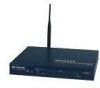
| The Firewall’s Front Panel |
19 |
| Figure 11: FVM318 Front Panel |
19 |
| Table 11: LED Descriptions |
20 |
| The Firewall’s Rear Panel |
21 |
| Figure 12: FVM318 Rear Panel |
21 |
| Chapter 2 Connecting the Firewall to the Internet |
23 |
| What You Will Need Before You Begin |
23 |
| 1. Have active Internet service such as that provided by an cable or DSL broadband account. |
23 |
| 2. Locate the Internet Service Provider (ISP) configuration information for your account. |
23 |
| 3. Connect the firewall to a cable or DSL modem and a computer as explained below. |
23 |
| Cabling and Computer Hardware Requirements |
23 |
| Network Configuration Requirements |
23 |
| Internet Configuration Requirements |
24 |
| Where Do I Get the Internet Configuration Parameters? |
24 |
| Procedure 2-1: Record Your Internet Connection Information |
25 |
| Connecting the FVM318 to Your LAN |
26 |
| Procedure 2-2: Connecting the Firewall to Your LAN |
26 |
| 1. Connect the firewall to your network. |
26 |
| 2. Log in to the firewall. |
26 |
| 3. Connect to the Internet. |
26 |
| 1. Connect the firewall. |
26 |
| a. Turn off your computer and cable or DSL Modem. |
26 |
| b. Disconnect the Ethernet cable (A) from your computer which connects to the modem. |
26 |
| Figure 21: Disconnect the cable or DSL Modem |
26 |
| c. Connect the Ethernet cable (A) from the modem to the FVM318’s Internet port. |
27 |
| Figure 22: Connect the cable or DSL Modem to the firewall |
27 |
| d. Connect the Ethernet cable (B) which came with the firewall from a local port on the router to your computer. |
27 |
| Figure 23: Connect the computers on your network to the firewall |
27 |
| e. Turn on the modem and wait about 30 seconds for the lights to stop blinking. |
28 |
| f. Turn on the firewall and wait for the Test light to stop blinking. |
28 |
| g. Now, turn on your computer. If you usually run software to log in to your Internet connection, do not run that software. |
28 |
| h. Now that the modem, firewall, and computer are turned on, verify the following: |
28 |
| 2. Log in to the firewall. |
28 |
| a. Log in to the firewall at its default address of http://192.168.0.1 using a browser like Internet Explorer or Netscape® Navigator. |
28 |
| Figure 24: Log in to the firewall. |
28 |
| Figure 25: Login window |
29 |
| b. For security reasons, the firewall has its own user name and password. When prompted, enter admin for the firewall user name and password for the firewall password, both in lower case letters. |
29 |
| 3. Connect to the Internet |
29 |
| Figure 26: Setup Wizard |
29 |
| a. You are now connected to the firewall. If you do not see the menu above, click the Setup Wizard link on the upper left of the main menu. |
30 |
| b. Click Next and follow the steps in the Setup Wizard for inputting the configuration parameters from your ISP to connect to the Internet. |
30 |
| c. When the firewall successfully detects an active Internet service, the Setup Wizard reports which connection type it discovered, and displays the appropriate configuration menu. If the Setup Wizard finds no connection, you will be prompted... |
30 |
| d. The Setup Wizard will report the type of connection it finds. The options are: |
30 |
| PPPoE Wizard-Detected Option |
31 |
| Figure 27: Setup Wizard menu for PPPoE accounts |
31 |
| Dynamic IP Wizard-Detected Option |
32 |
| Figure 28: Setup Wizard menu for Dynamic IP address accounts |
32 |
| Fixed IP Account Wizard-Detected Option |
33 |
| Figure 29: Setup Wizard menu for Fixed IP address accounts |
33 |
| Manually Configuring Your Internet Connection |
34 |
| Figure 210: Browser-based configuration Basic Settings menus |
34 |
| Procedure 2-3: Configuring the Internet Connection Manually |
35 |
| 1. Log in to the firewall at its default address of http://192.168.0.1 using a browser like Internet Explorer or Netscape® Navigator. |
35 |
| 2. Click the Basic Settings link under the Setup section of the main menu. |
35 |
| 3. If your Internet connection does not require a login, click No at the top of the Basic Settings menu and fill in the settings according to the instructions below. If your Internet connection does require a login, click Yes, and skip to step 3. |
35 |
| a. Enter your Account Name (may also be called Host Name) and Domain Name. These parameters may be necessary to access your ISP’s services such as mail or news servers. |
35 |
| b. Internet IP Address: If your ISP has assigned you a permanent, fixed (static) IP address for your PC, select “Use static IP address”. Enter the IP address that your ISP assigned. Also enter the netmask and the Gateway IP address. The Gatew... |
35 |
| c. Domain Name Server (DNS) Address: If you know that your ISP does not automatically transmit DNS addresses to the firewall during login, select “Use these DNS servers” and enter the IP address of your ISP’s Primary DNS Server. If a Secondar... |
35 |
| d. Gateway’s MAC Address: This section determines the Ethernet MAC address that will be used by the firewall on the Internet port. Some ISPs will register the Ethernet MAC address of the network interface card in your PC when your account is ... |
35 |
| e. Click Apply to save your settings. |
35 |
| 4. If your Internet connection does require a login, fill in the settings according to the instructions below. Select Yes if you normally must launch a login program such as Enternet or WinPOET in order to access the Internet. |
36 |
| a. Select your Internet service provider from the drop-down list. |
36 |
| Figure 211: Basic Settings ISP list |
36 |
| b. The screen will change according to the ISP settings requirements of the ISP you select. |
36 |
| c. Fill in the parameters for your ISP according to the Wizard-detected procedures starting on page 29. |
36 |
| d. Click Apply to save your settings. |
36 |
| Chapter 3 Wireless Configuration |
37 |
| Considerations For A Wireless Network |
37 |
| Observe Performance, Placement and Range Guidelines |
37 |
| Implement Appropriate Wireless Security |
38 |
| Figure 31: FVM318 wireless data security options |
38 |
| Understanding Wireless Settings |
39 |
| Figure 32: Wireless Settings menu |
39 |
| Wireless Network Settings |
39 |
| Restricting Access Based on the Wireless Card Access List |
40 |
| Figure 33: Wireless Card Access List menu |
40 |
| Choosing Authentication and Security Encryption Methods |
40 |
| Figure 34: Encryption Strength |
40 |
| Automatic Authentication Scheme Selection |
40 |
| Encryption Strength Choices |
41 |
| Disable |
41 |
| IPSec |
41 |
| Figure 35: IPSec main or aggressive mode settings |
41 |
| Figure 36: IPSec encryption protocol |
42 |
| 64 or 128 bit WEP |
42 |
| Figure 37: Encryption Strength |
42 |
| Figure 38: 64 or 128 bit WEP encryption strength |
43 |
| Procedure 3-1: Set Up and Test Basic Wireless Connectivity |
43 |
| 1. Log in to the FVM318 firewall at its default LAN address of http://192.168.0.1 with its default user name of admin and default password of password, or using whatever LAN address and password you have set up. |
44 |
| 2. Click the Wireless Settings link in the main menu of the FVM318 firewall. |
44 |
| Figure 39: Wireless Settings menu |
44 |
| 3. Choose a suitable descriptive name for the wireless network name (SSID). In the SSID box, enter a value of up to 32 alphanumeric characters. The default SSID is Wireless. |
44 |
| 4. Set the Region. Select the region in which the wireless interface will operate. |
44 |
| 5. Set the Channel. The default channel is 6. |
44 |
| 6. For initial configuration and test, leave the Wireless Card Access List set to “Everyone” and the Encryption Strength set to “Disabled.” |
44 |
| 7. Click Apply to save your changes. |
44 |
| 8. Configure and test your PCs for wireless connectivity. |
45 |
| Procedure 3-2: Restrict Wireless Access by MAC Address |
45 |
| 1. Log in to the FVM318 firewall at its default LAN address of http://192.168.0.1 with its default user name of admin and default password of password, or using whatever LAN address and password you have set up. |
45 |
| 2. Click the Wireless Settings link in the main menu of the FVM318 firewall. |
45 |
| 3. From the Wireless Settings menu, click the Trusted PCs button to display the Wireless Access menu shown below. |
45 |
| Figure 310. Wireless Access menu |
45 |
| 4. Enter the MAC address of the authorized PC. Enter a descriptive name for the PC in the Device Name field. The MAC address is usually printed on the wireless card, or it may appear in the firewall’s “Attached Devices” DHCP table. |
46 |
| 5. Click Add to save your entry. |
46 |
| 6. Click Back to return to the Wireless Settings menu |
46 |
| 7. Be sure that the Trusted PCs only radio button is selected, then click Apply. |
46 |
| Procedure 3-3: Configure WEP |
46 |
| 1. Log in to the FVM318 firewall at its default LAN address of http://192.168.0.1 with its default user name of admin and default password of password, or using whatever LAN address and password you have set up. |
46 |
| 2. Click the Wireless Settings link in the main menu of the FVM318 firewall. |
46 |
| 3. From the Security Encryption menu drop-down list, select the WEP encryption type you will use. |
47 |
| Figure 311. Wireless Settings encryption menu |
47 |
| 4. You can manually or automatically program the four data encryption keys. These values must be identical on all PCs and Access Points in your network. |
47 |
| 5. Click Apply to save your settings. |
47 |
| Configuring IPSec Wireless Connections |
48 |
| Figure 312. Configuring basic wireless IPSec VPN tunnel connections |
48 |
| Procedure 3-4: Configure Basic IPSec Wireless Connections |
49 |
| 1. Configure the FVM318 settings. |
49 |
| a. Log in to the FVM318 at http://192.168.0.1 with its default user name of admin and default password of password, or using whatever user name, password you have set up. |
49 |
| b. Click the Wireless link in the main menu Setup section to display the menu shown below. |
49 |
| Figure 313. Wireless Settings menu, IPSec selected |
49 |
| c. Click the Encryption Strength drop-down list box and select IPSec. The Wireless Settings menu will change to display the list of IPSec connections, as shown in Figure 313: |
49 |
| d. Click Add to display the IPSec client setting menu, as shown below. |
50 |
| Figure 314. IPSec Client Settings menu |
50 |
| e. Enter a descriptive name for this PC in Connection Name. This name is for your convenience only, and is not used in the VPN negotiation. |
50 |
| f. Enter the user name. An email address is an easy to remember user name. |
50 |
| g. Enter a Pre-Shared Key value for this connection. |
50 |
| h. Use the default Aggressive Mode and AES - 256 settings. |
50 |
| 2. Install the SafeNet SoftRemote Basic VPN client software. |
50 |
| a. Place the FVM318 Resource CD in your CD drive. |
50 |
| b. Install the SafeNet SoftRemote Basic VPN client. |
50 |
| Figure 315. SafeNet system tray icon with disabled indicator |
50 |
| 3. Configure the SoftRemote Basic VPN Client. |
51 |
| a. In the taskbar tray, right-click on the SafeNet icon and select Edit Security Policy in the VPN client task menu, as shown below. |
51 |
| Figure 316. SafeNet system tray icon menu |
51 |
| Figure 317. SafeNet basic configuration menu |
51 |
| b. In most cases, you can leave the IPSec Gateway as “LAN Gateway”, which indicates the firewall. If you are not using the firewall as your network’s default gateway, change IPSec Gateway to indicate either the IP Address or the network name ... |
52 |
| c. Enter the User Name and the Pre-Shared Key value that you programmed for this PC in the firewall’s IPSec Client Settings menu. |
52 |
| d. Click OK. |
52 |
| e. In the taskbar tray, right-click on the SafeNet icon and select Activate Security Policy in the task menu. The SafeNet icon will now appear without the red bar, as shown below. |
52 |
| Figure 318. SafeNet system tray icon showing enabled condition |
52 |
| 4. Test the SoftRemote Basic VPN Connection. |
52 |
| a. On the Windows taskbar, click the Start button, and then click Run. |
52 |
| b. Type ping -t 192.168.0.1 , and then click OK. |
52 |
| Figure 319. Run Ping from Windows Start Menu |
52 |
| Figure 320. Ping results |
53 |
| Figure 321. SafeNet system tray icon showing ON condition |
53 |
| c. Once the connection is established, you can open the browser of the PC and browse. |
53 |
| Using SoftRemoteLT Instead of SoftRemote Basic |
53 |
| Procedure 3-5: Configuring the SoftRemoteLT Full Client |
54 |
| 1. Install the SafeNet SoftRemoteLT Full VPN Client |
54 |
| 2. Open the Security Policy Editor. |
54 |
| Figure 322. SafeNet Security Policy Editor |
54 |
| 3. Create a VPN Connection. |
54 |
| a. From the Edit menu at the top of the Security Policy Editor window, click Add, then Connection. A New Connection listing will appear in the list of policies. |
55 |
| Figure 323. SafeNet Security Policy Editor new connection menu |
55 |
| b. Click and rename the New Connection list item to indicate that this is the policy for your local wireless connection, such as Wireless. |
55 |
| c. Select Secure on the right side of the Security Policy Editor window in the Connection Security box. |
55 |
| d. Select IP Subnet in the ID Type menu. |
55 |
| e. Type 0.0.0.0 in the Subnet and Mask fields. |
55 |
| f. Select All in the Protocol menu to allow all traffic through the VPN tunnel. |
55 |
| g. Check Connect using Secure Gateway Tunnel. |
55 |
| h. Select Any in the ID Type menu below the checkbox. |
55 |
| i. Select Gateway IP Address in the box to the right of ID Type. |
55 |
| j. Enter the LAN IP Address of the FVM318 firewall in the lower right box (usually 192.168.0.1). |
55 |
| 4. Configure the Security Policy. |
56 |
| a. In the Network Security Policy list on the left side of the Security Policy Editor window, expand the new connection by double clicking its name or clicking on the “+” symbol. |
56 |
| b. Click on the Security Policy subheading to show the Security Policy menu. |
56 |
| Figure 324. SafeNet Security Policy Editor edit security policy menu |
56 |
| c. Select Aggressive Mode in the Select Phase 1 Negotiation Mode box. |
56 |
| d. Check the Enable Perfect Forward Secrecy (PFS) checkbox. |
56 |
| e. Select Diffie-Helman Group 2 for PFS Key Group. |
56 |
| f. Check the Enable Replay Detection checkbox. |
56 |
| 5. Configure the VPN Client Identity |
56 |
| a. Click on My Identity in the Network Security Policy list on the left side of the Security Policy Editor window. |
57 |
| Figure 325. SafeNet Security Policy Editor edit identity menu |
57 |
| b. Choose None in the Select Certificate menu. |
57 |
| c. Select Domain Name in the ID Type menu. |
57 |
| d. In the box below ID Type, enter the user name that you configured in the FVM318 firewall. |
57 |
| e. Select Disabled in the Virtual Adapter box. |
57 |
| f. In the Internet Interface box, select your wireless adapter or you may choose Any if you will be switching between adapters or if you have only one adapter. |
57 |
| g. Click the Pre-Shared Key button. |
57 |
| h. Click the Enter Key button in the Pre-Shared Key dialog box. |
57 |
| i. Enter the Pre-Shared Key that you configured in the FVM318 firewall and click OK. Note that this field is case sensitive. |
57 |
| 6. Configure VPN Client Authentication Proposal |
57 |
| a. In the Network Security Policy list on the left side of the Security Policy Editor window, expand the Security Policy heading by double clicking its name or clicking on the “+” symbol. |
57 |
| b. Expand the Authentication subheading by double clicking its name or clicking on the “+” symbol. Then select Proposal 1 below Authentication. |
58 |
| c. Select Pre-Shared key in the Authentication Method menu. |
58 |
| d. Select AES-256 in the Encrypt Alg menu. If your VPN client does not offer this selection, select Triple DES. |
58 |
| e. Select SHA-1 in the Hash Alg menu. |
58 |
| f. Select Seconds and enter 21600 in the SA Life menu. |
58 |
| g. Select Diffie-Hellman Group 2 in the Key Group menu. |
58 |
| 7. Configure VPN Client Key Exchange Proposal. |
58 |
| a. Expand the Key Exchange subheading by double clicking its name or clicking on the “+” symbol. |
58 |
| b. Select Proposal 1 below Key Exchange. |
58 |
| c. In the SA Life menu, select Seconds and enter 21600. |
58 |
| d. Select None in the Compression menu. |
58 |
| e. Check the Encapsulation Protocol (ESP) checkbox. |
58 |
| f. Select AES-256 in the Encrypt Alg menu. If your VPN client does not offer this selection, select Triple DES. |
58 |
| g. Select SHA-1 in the Hash Alg menu. |
58 |
| h. Select Tunnel in the Encapsulation menu. |
58 |
| i. Leave the Authentication Protocol (AH) checkbox unchecked. |
58 |
| 8. Save the VPN Client Settings. |
58 |
| Chapter 4 Protecting Your Network |
59 |
| Protecting Access to Your FVM318 firewall |
59 |
| Procedure 4-1: Changing the Administrator Password |
59 |
| 1. Log in to the firewall at its default LAN address of http://192.168.0.1 with its default user name of admin and default password of password, or using whatever password and LAN address you have chosen for the firewall. |
59 |
| 2. From the main menu of the browser interface, under the Maintenance heading, select Set Password to bring up the menu shown below. |
60 |
| Figure 41: Set Password menu |
60 |
| 3. To change the password, first enter the old password, and then enter the new password twice. |
60 |
| 4. Click Apply to save your changes. |
60 |
| Procedure 4-2: Changing the Administrator Login Timeout |
61 |
| 1. In the Set Password menu, type a number in ‘Administrator login times out’ field. The suggested default value is 5 minutes. |
61 |
| 2. Click Apply to save your changes or click Cancel to keep the current period. |
61 |
| Configuring Basic Firewall Services |
61 |
| Blocking Functions, Keywords, Sites, and Services |
61 |
| Procedure 4-3: Blocking Functions, Keywords, and Sites |
62 |
| 1. Log in to the firewall at its default LAN address of http://192.168.0.1 with its default user name of admin, default password of password, or using whatever password and LAN address you have chosen for the firewall. |
62 |
| 2. Click the Block Sites link of the Security section of the main menu to view the screen below. |
62 |
| Figure 42: Block Sites menu |
62 |
| 3. To block ActiveX, Java, Cookies, or Web Proxy functions for all Internet sites, click the check box next to the function and then click Apply. |
62 |
| 4. To enable keyword blocking, check “Turn keyword blocking on”, enter a keyword or domain in the Keyword box, click Add Keyword, then click Apply. |
62 |
| 5. To delete a keyword or domain, select it from the list, click Delete Keyword, then click Apply. |
63 |
| 6. To specify a Trusted User, enter that PC’s IP address in the Trusted User box and click Apply. |
63 |
| Blocking Services |
63 |
| Procedure 4-4: Configuring Services Blocking |
64 |
| 1. Log in to the firewall at its default LAN address of http://192.168.0.1 with its default user name of admin, default password of password, or using whatever password and LAN address you have chosen for the firewall. |
64 |
| 2. Click the Block Services link of the Security section of the main menu to display this screen. |
64 |
| Figure 43: Block Services menu |
64 |
| 3. Modify the menu below to define or edit how a service is regulated. |
64 |
| Figure 44: Add Block Services menu |
64 |
| 4. Click Apply to save your definition. |
65 |
| Setting Times and Scheduling Firewall Services |
65 |
| Procedure 4-5: Setting Your Time Zone |
66 |
| 1. Log in to the firewall at its default LAN address of http://192.168.0.1 with its default user name of admin, default password of password, or using whatever password and LAN address you have chosen for the firewall. |
66 |
| 2. Click on the Schedule link of the Security menu to display the menu shown below. |
66 |
| Figure 45: Schedule Services menu |
66 |
| 3. Select your Time Zone. This setting will be used for the blocking schedule according to your local time zone and for time-stamping log entries. |
67 |
| 4. The firewall has a list of publicly available NTP servers. If you would prefer to use a particular NTP server as the primary server, enter its IP address under Use this NTP Server. |
67 |
| 5. Click Apply to save your settings. |
67 |
| Procedure 4-6: Scheduling Firewall Services |
67 |
| 1. Log in to the firewall at its default LAN address of http://192.168.0.1 with its default user name of admin, default password of password, or using whatever password and LAN address you have chosen for the firewall. |
67 |
| 2. Click on the Schedule link of the Security menu. |
67 |
| 3. To block Internet services based on a schedule, select Every Day or select one or more days. If you want to limit access completely for the selected days, select All Day. Otherwise, to limit access during certain times for the selected day... |
67 |
| 4. Click Apply to save your changes. |
67 |
| Chapter 5 Virtual Private Networking |
69 |
| FVM318 VPN Overview |
69 |
| Figure 51: Secure access through VPN tunnels |
69 |
| FVM318 VPN Configuration Planning |
71 |
| Procedure 5-1: Configuring a Network to Network VPN Tunnel |
72 |
| Figure 52: LAN to LAN VPN access from an FVM318 to an FVM318 |
72 |
| Network to Network VPN Tunnel Configuration Worksheet |
72 |
| 1. Set up the two LANs to have different IP address ranges. |
73 |
| a. Log in to the FVM318 on LAN A at its default LAN address of http://192.168.0.1 with its default user name of admin and password of password. Click the LAN IP Setup link in the main menu Advanced section to display the LAN TCP/IP Setup menu... |
73 |
| Figure 53: Configuring the Local LAN (A) via the LAN IP Setup Menu |
73 |
| b. For this example, configure the FVM318 settings on LANs A and B as follows: |
73 |
| Network Configuration Settings |
73 |
| c. Click Apply. Because you changed the firewall’s IP address, you are now disconnected. |
73 |
| d. Reboot all PCs on network A. |
73 |
| 2. Configure the VPN settings on each FVM318. |
74 |
| a. From Setup section of the main menu of the FVM318, click the VPN Settings link. Click Add. The VPN Settings - Main Mode window opens as shown below: |
74 |
| Figure 54: VPN Settings - Main Mode IKE Edit menu |
74 |
| b. Fill in the Connection Name VPN settings as illustrated. |
74 |
| c. Under Secure Association, select Main Mode and fill in the settings below. |
75 |
| d. If you need to run Microsoft networking functions such as Network Neighborhood, click the NETBIOS Enable check box to allow NETBIOS traffic over the VPN tunnel. |
75 |
| e. Click Apply to save the Security Association tunnel settings into the table. |
75 |
| 3. Check the VPN Connection |
76 |
| a. Using our example, from a PC attached to the FVM318 on LAN A, on the Windows taskbar click the Start button, and then click Run. |
76 |
| b. Type ping -t 192.168.0.1 , and then click OK. |
76 |
| Figure 55: Running a Ping test from Windows |
76 |
| c. This will cause a continuous ping to be sent to the first FVM318. After between several seconds and two minutes, the ping response should change from “timed out” to “reply.” |
76 |
| Figure 56: Ping test results |
76 |
| Procedure 5-2: Configuring a Remote PC to Network VPN |
76 |
| Figure 57: PC to LAN VPN access from a PC to an FVM318 |
77 |
| PC to Network VPN Tunnel Configuration Worksheet |
77 |
| 1. Configure the VPN Tunnel on the FVM318 on LAN A. |
78 |
| a. From the Setup Menu, click the VPN Settings link, then click Add to configure a new VPN tunnel. The VPN Settings - IKE window opens as shown below: |
78 |
| Figure 58: VPN Edit menu for connecting with a VPN client |
78 |
| b. Fill in the Connection Name VPN settings as illustrated. |
78 |
| c. Under Secure Association, select Main Mode and fill in the settings below. |
79 |
| d. If you need to run Microsoft networking functions such as Network Neighborhood, click the NETBIOS Enable check box to allow NETBIOS traffic over the VPN tunnel. |
79 |
| e. Click Apply to save the Security Association tunnel settings into the table. |
79 |
| 2. Install land Configure the SafeNet VPN Client Software on the PC. |
79 |
| a. Install the SafeNet Secure VPN Client. |
79 |
| Figure 59: Security Policy Editor New Connection |
80 |
| b. Add a new connection |
80 |
| c. Configure the Security Policy in the SafeNet VPN Client Software. |
81 |
| Figure 510: Security Policy Editor Security Policy |
81 |
| d. Configure the Global Policy Settings. |
82 |
| Figure 511: Security Policy Editor Global Policy Options |
82 |
| e. Configure the VPN Client Identity |
82 |
| Figure 512: Security Policy Editor My Identity |
83 |
| f. Configure the VPN Client Authentication Proposal. |
83 |
| g. Configure the VPN Client Key Exchange Proposal. |
84 |
| h. Save the VPN Client Settings. |
84 |
| 3. Check the VPN Connection. |
85 |
| a. Establish an Internet connection from the PC. |
85 |
| b. On the Windows taskbar, click the Start button, and then click Run. |
85 |
| c. Type ping -t 192.168.3.1 , and then click OK. |
85 |
| Figure 513: Running a Ping test to the LAN from the PC |
85 |
| Figure 514: Ping test results |
85 |
| Monitoring the PC VPN Connection Using SafeNet Tools |
86 |
| Figure 515: Log Viewer screen |
86 |
| Figure 516: Connection Monitor screen |
86 |
| Procedure 5-3: Deleting a Security Association |
87 |
| 1. Log in to the firewall. |
87 |
| 1. Click the VPN Settings link. |
87 |
| 2. In the VPN Settings Security Association table, select the radio button for the security association to be deleted. |
87 |
| 3. Click the Delete button. |
87 |
| 4. Click the Update button. |
87 |
| Manual Keying |
87 |
| Procedure 5-4: Using Manual Keying as an Alternative to IKE |
87 |
| 1. When editing the VPN Settings, you may select manual keying. At that time, the edit menu changes to look like the screen below: |
87 |
| Figure 517: VPN Edit menu for Manual Keying |
88 |
| 2. Incoming SPI - Enter a Security Parameter Index that the remote host will send to identify the Security Association (SA). This will be the remote host’s Outgoing SPI. |
88 |
| 3. Outgoing SPI - Enter a Security Parameter Index that this firewall will send to identify the Security Association (SA). This will be the remote host’s Incoming SPI. |
88 |
| 4. For Encryption Protocol, select one: |
89 |
| Figure 518: VPN encryption options |
89 |
| a. Null - Fastest, but no security. |
89 |
| b. DES - The Data Encryption Standard (DES) processes input data that is 64 bits wide, encrypting these values using a 56 bit key. Faster but less secure than 3DES or AES. |
89 |
| c. 3DES - (Triple DES) achieves a higher level of security by encrypting the data three times using DES with three different, unrelated keys. |
89 |
| d. AES - 128, - 192, or - 256. Most secure. Advanced Encryption Standard, a symmetric 128-bit block data encryption technique. It is an iterated block cipher with a variable block length and a variable key length. The block length and the key... |
89 |
| e. Enter a hexadecimal Encryption Key |
89 |
| 5. Select the Authentication Protocol |
89 |
| 6. Enter 32 hexadecimal characters for the Authentication Key. The authentication key must match exactly the key used by the remote router or host. |
89 |
| 7. Click the NETBIOS Enable check box to allow NETBIOS over the VPN tunnel. |
89 |
| 8. Click Apply to enter the SA into the table. |
89 |
| Blank VPN Tunnel Configuration Worksheets |
90 |
| Table 5-1: Network to Network IKE VPN Tunnel Configuration Worksheet |
90 |
| Table 5-2: PC to Network IKE VPN Tunnel Settings Configuration Worksheet |
91 |
| Chapter 6 Managing Your Network |
93 |
| Network Management Information |
93 |
| Viewing Router Status and Usage Statistics |
93 |
| Figure 61: Router Status screen |
93 |
| Table 61. Router Status Fields |
94 |
| Figure 62. Router Statistics screen |
95 |
| Table 62. Router Statistics Fields |
95 |
| Viewing Attached Devices |
96 |
| Figure 63: Attached Devices menu |
96 |
| Viewing, Selecting, and Saving Logged Information |
97 |
| Figure 64: Security Logs menu |
97 |
| Table 6-5: Security Log entry descriptions |
98 |
| Table 6-6: Security Log action buttons |
98 |
| Selecting What Information to Include in the Log |
98 |
| Enabling SYSLOG |
99 |
| Examples of log messages |
99 |
| Activation and Administration |
99 |
| Dropped Packets |
99 |
| Enabling Security Event E-mail Notification |
100 |
| Figure 67: E-mail menu |
100 |
| Backing Up, Restoring, or Erasing Your Settings |
101 |
| Procedure 6-1: Backup the Configuration to a File |
101 |
| 1. Log in to the firewall at its default LAN address of http://192.168.0.1 with its default user name of admin, default password of password, or using whatever password and LAN address you have chosen for the firewall. |
101 |
| 2. From the Maintenance heading of the main menu, select Backup to view the menu seen below. |
102 |
| Figure 68: Settings Backup menu |
102 |
| 3. Click Backup to save a copy of the current settings. |
102 |
| 4. Store the.cfg file on a computer on your network. |
102 |
| Procedure 6-2: Restore a Configuration from a File |
102 |
| 1. Log in to the firewall at its default LAN address of http://192.168.0.1 with its default user name of admin, default password of password, or using whatever password and LAN address you have chosen for the firewall. |
102 |
| 2. From the Maintenance heading of the main menu, select the Settings Backup menu as seen in Figure 68. |
102 |
| 3. Enter the full path to the file on your network or click the Browse button to browse to the file. |
102 |
| 4. When you have located the .cfg file, click the Restore button to upload the file to the firewall. |
102 |
| 5. The firewall will then reboot automatically. |
102 |
| Procedure 6-3: Erase the Configuration |
102 |
| 1. To erase the configuration, from the Maintenance menu Settings Backup link, click the Erase button on the screen. |
103 |
| 2. The firewall will then reboot automatically. |
103 |
| Running Diagnostic Utilities and Rebooting the Router |
103 |
| Figure 69: Diagnostics menu |
104 |
| Enabling Remote Management |
104 |
| Procedure 6-4: Configure Remote Management |
104 |
| 1. Log in to the firewall at its default LAN address of http://192.168.0.1 with its default user name of admin, default password of password, or using whatever password and LAN address you have chosen for the firewall. |
104 |
| 2. Select the Allow Remote Management check box. |
104 |
| 3. Specify what external addresses will be allowed to access the firewall’s remote management. For security, NETGEAR recommends that you restrict access to as few external IP addresses as practical. |
105 |
| a. To allow access from any IP address on the Internet, select Everyone. |
105 |
| b. To allow access from a range of IP addresses on the Internet, select IP address range. Enter a beginning and ending IP address to define the allowed range. |
105 |
| c. To allow access from a single IP address on the Internet, select Only this PC. Enter the IP address that will be allowed access. |
105 |
| 4. Specify the Port Number that will be used for accessing the management interface. |
105 |
| 5. Click Apply to have your changes take effect. |
105 |
| Upgrading the Router’s Firmware |
105 |
| Procedure 6-5: Router Upgrade |
106 |
| 1. Download and unzip the new software file from NETGEAR. |
106 |
| 2. Log in to the firewall at its default LAN address of http://192.168.0.1 with its default user name of admin, default password of password, or using whatever password and LAN address you have chosen for the firewall. |
106 |
| 3. From the main menu of the browser interface, under the Maintenance heading, click Router Upgrade to display the menu shown below. |
106 |
| Figure 610: Router Upgrade menu |
106 |
| 4. In the Router Upgrade menu, click the Browse button to locate the binary (.BIN or .IMG) upgrade file. |
106 |
| 5. Click Upload to load the firmware into the firewall. |
106 |
| Chapter 7 Advanced Configuration |
107 |
| Configuring Advanced Security |
107 |
| Setting Up A Default DMZ Server |
107 |
| 1. Click Default DMZ Server. |
108 |
| 2. Type the IP address for that server. |
108 |
| 3. Click Apply. |
108 |
| Respond to Ping on Internet WAN Port |
108 |
| Configuring LAN IP Settings |
108 |
| LAN TCP/IP Setup |
108 |
| MTU Size |
110 |
| 1. Under MTU Size, select Custom. |
110 |
| 2. Enter a new size between 64 and 1500. |
110 |
| 3. Click Apply to save the new configuration. |
110 |
| Using the Router as a DHCP Server |
110 |
| Procedure 7-1: Using Reserved IP Addresses |
111 |
| 1. Click the Add button. |
111 |
| 2. In the IP Address box, type the IP address to assign to the PC or server. Choose an IP address from the router’s LAN subnet, such as 192.168.0.X. |
111 |
| 3. Type the MAC Address of the PC or server. |
111 |
| 4. Click Apply to enter the reserved address into the table. |
111 |
| 1. Click the radio button next to the reserved address to select the entry you want to edit or delete. |
111 |
| 2. Click Edit or Delete. |
111 |
| Procedure 7-2: Configuring LAN TCP/IP Settings |
112 |
| 1. Log in to the firewall at its default LAN address of http://192.168.0.1 with its default user name of admin, default password of password, or using whatever password and LAN address you have chosen for the firewall. |
112 |
| 2. From the main menu, under Advanced, click the LAN IP Setup link to view the menu, shown below. |
112 |
| Figure 71: LAN IP Setup Menu |
112 |
| 3. Enter the UPnP, TCP/IP, MTU, or DHCP parameters. |
112 |
| 4. Click Apply to save your changes. |
112 |
| Configuring Dynamic DNS |
113 |
| Procedure 7-3: Configuring Dynamic DNS |
113 |
| 1. Log in to the firewall at its default LAN address of http://192.168.0.1 with its default user name of admin, default password of password, or using whatever password and LAN address you have chosen for the firewall. |
113 |
| 2. From the main menu of the browser interface, under Advanced, click on Dynamic DNS. |
113 |
| 3. Access the website of one of the dynamic DNS service providers whose names appear in the ‘Select Service Provider’ box, and register for an account. For example, for dyndns.org, go to www.dyndns.org. |
113 |
| 4. Select the “Use a dynamic DNS service” check box. |
113 |
| 5. Select the name of your dynamic DNS Service Provider. |
113 |
| 6. Type the Host Name that your dynamic DNS service provider gave you. The dynamic DNS service provider may call this the domain name. If your URL is myName.dyndns.org, then your Host Name is “myName.” |
113 |
| 7. Type the user name for your dynamic DNS account. |
113 |
| 8. Type the password (or key) for your dynamic DNS account. |
113 |
| 9. If your dynamic DNS provider allows the use of wildcards in resolving your URL, you may select the Use wildcards check box to activate this feature. For example, the wildcard feature will cause *.yourhost.dyndns.org to be aliased to the sa... |
113 |
| 10. Click Apply to save your configuration. |
113 |
| Using Static Routes |
114 |
| Procedure 7-4: Configuring Static Routes |
115 |
| 1. Log in to the firewall at its default LAN address of http://192.168.0.1 with its default user name of admin, default password of password, or using whatever password and LAN address you have chosen for the firewall. |
115 |
| 2. From the main menu of the browser interface, under Advanced, click on Static Routes to view the Static Routes table, shown below. |
115 |
| Figure 72: Static Routes Table |
115 |
| 3. To add or edit a Static Route, follow these steps: |
115 |
| a. Click the Edit button to open the Edit Menu, shown in Figure 73. |
115 |
| Figure 73: Static Route Entry and Edit Menu |
115 |
| b. Type a route name for this static route in the Route Name box under the table. This is for identification purpose only. |
116 |
| c. Click the Active check box to make this route effective. |
116 |
| d. Click the Private check box if you want to limit access to the LAN only. The static route will not be reported in RIP. |
116 |
| e. Type the Destination IP Address of the final destination. |
116 |
| f. Type the IP Subnet Mask for this destination. If the destination is a single host, type 255.255.255.255. |
116 |
| g. Type the Gateway IP Address, which must be a router on the same LAN segment as the firewall. |
116 |
| h. Type a number between 1 and 15 as the Metric value. This represents the number of routers between your network and the destination. Usually, a setting of 2 or 3 works, but if this is a direct connection, set it to 1. |
116 |
| 4. Click Apply to have the static route entered into the table. |
116 |
| Chapter 8 Troubleshooting |
117 |
| Basic Functions |
117 |
| 1. When power is first applied, verify that the Power LED is on. |
117 |
| 2. Verify that the Test LED lights within a few seconds, indicating that the self-test procedure is running. |
117 |
| 3. After approximately 10 seconds, verify that: |
117 |
| a. The Test LED is not lit. |
117 |
| b. The Local port Link LEDs are lit for any local ports that are connected. |
117 |
| c. The Internet Link port LED is lit. |
117 |
| Power LED Not On |
118 |
| Test LED Never Turns On or Test LED Stays On |
118 |
| Local or Internet Port Link LEDs Not On |
118 |
| Troubleshooting the Web Configuration Interface |
119 |
| Troubleshooting the ISP Connection |
120 |
| 1. Launch your browser and select an external site such as www.netgear.com |
120 |
| 2. Access the main menu of the firewall’s configuration at http://192.168.0.1 |
120 |
| 3. Under the Maintenance heading, select Router Status |
120 |
| 4. Check that an IP address is shown for the WAN Port If 0.0.0.0 is shown, your firewall has not obtained an IP address from your ISP. |
120 |
| 1. Turn off power to the cable or DSL modem. |
120 |
| 2. Turn off power to your firewall. |
120 |
| 3. Wait five minutes and reapply power to the cable or DSL modem. |
120 |
| 4. When the modem’s LEDs indicate that it has reacquired sync with the ISP, reapply power to your firewall. |
120 |
| Troubleshooting a TCP/IP Network Using a Ping Utility |
121 |
| Procedure 8-5: Testing the LAN Path to Your Firewall |
122 |
| 1. From the Windows toolbar, click on the Start button and select Run. |
122 |
| 2. In the field provided, type Ping followed by the IP address of the firewall, as in this example: |
122 |
| 3. Click on OK. |
122 |
| Procedure 8-6: Testing the Path from Your PC to a Remote Device |
123 |
| Restoring the Default Configuration and Password |
123 |
| Procedure 8-7: Using the Default Reset button |
124 |
| 1. Press and hold the Default Reset button until the Test LED turns on (about 10 seconds). |
124 |
| 2. Release the Default Reset button and wait for the firewall to reboot. |
124 |
| Problems with Date and Time |
124 |
| Appendix A Technical Specifications |
125 |
| Appendix B Network, Routing, Firewall, and Wireless Basics |
127 |
| Related Publications |
127 |
| Basic Router Concepts |
127 |
| What is a Router? |
128 |
| Routing Information Protocol |
128 |
| IP Addresses and the Internet |
128 |
| Figure 81: Three Main Address Classes |
129 |
| Netmask |
130 |
| Subnet Addressing |
131 |
| Figure 82: Example of Subnetting a Class B Address |
131 |
| Table 81. Netmask Notation Translation Table for One Octet |
132 |
| Table 82. Netmask Formats |
132 |
| Private IP Addresses |
133 |
| Single IP Address Operation Using NAT |
134 |
| Figure 83: Single IP Address Operation Using NAT |
134 |
| MAC Addresses and Address Resolution Protocol |
135 |
| Related Documents |
135 |
| Domain Name Server |
135 |
| IP Configuration by DHCP |
136 |
| Internet Security and Firewalls |
136 |
| What is a Firewall? |
137 |
| Stateful Packet Inspection |
137 |
| Denial of Service Attack |
137 |
| Wireless Networking |
138 |
| Wireless Network Configuration |
138 |
| Ad Hoc Mode (Peer-to-Peer Workgroup) |
138 |
| Infrastructure Mode |
138 |
| Extended Service Set Identification (ESSID) |
139 |
| Authentication and WEP Encryption |
139 |
| 802.11b Authentication |
139 |
| 1. Turn on the wireless station. |
139 |
| 2. The station listens for messages from any access points that are in range. |
140 |
| 3. The station finds a message from an access point that has a matching SSID. |
140 |
| 4. The station sends an authentication request to the access point. |
140 |
| 5. The access point authenticates the station. |
140 |
| 6. The station sends an association request to the access point. |
140 |
| 7. The access point associates with the station. |
140 |
| 8. The station can now communicate with the Ethernet network through the access point. |
140 |
| Open System Authentication |
140 |
| 1. The station sends an authentication request to the access point. |
140 |
| 2. The access point authenticates the station. |
140 |
| 3. The station associates with the access point and joins the network. |
140 |
| Figure 84: 802.11b open system authentication |
141 |
| Shared Key Authentication |
141 |
| 1. The station sends an authentication request to the access point. |
141 |
| 2. The access point sends challenge text to the station. |
141 |
| 3. The station uses its configured 64-bit or 128-bit default key to encrypt the challenge text, and sends the encrypted text to the access point. |
141 |
| 4. The access point decrypts the encrypted text using its configured WEP Key that corresponds to the station’s default key. The access point compares the decrypted text with the original challenge text. If the decrypted text matches the origi... |
141 |
| 5. The station connects to the network. |
141 |
| Figure 85: 802.11b shared key authentication |
142 |
| Overview of WEP Parameters |
142 |
| Key Size |
143 |
| WEP Configuration Options |
143 |
| Wireless Channel Selection |
144 |
| Table 81. 802.11 Radio Frequency Channels |
144 |
| Ethernet Cabling |
145 |
| Table 82. UTP Ethernet cable wiring, straight-through |
145 |
| Uplink Switches, Crossover Cables, and MDI/MDIX Switching |
145 |
| Cable Quality |
146 |
| How Does VPN Work? |
147 |
| Figure 86: VPN overview |
147 |
| IKE: Managing and Exchanging Keys |
147 |
| Negotiating the SA - the Internet Key Exchange (IKE) |
148 |
| 1. Phase 1. The peers establish a secure channel. After Phase 1, all IKE packets are encrypted. |
148 |
| 2. Phase 2. The peers negotiate a general purpose SA. |
148 |
| Authentication: Phase 1 |
148 |
| a. Both agree on basic algorithms and hashes. |
148 |
| b. Both exchange Diffie-Hellman public keys and pass nonces. Nonce is a cryptographic term for a fresh random number that is used only once. |
148 |
| c. Both parties verify each other’s identity. This exchange is already encrypted. |
148 |
| a. The initiator generates a Diffie-Hellman public value, sending it with the nonce. |
148 |
| b. The responder sends its own Diffie-Hellman value. |
149 |
| c. The initiator confirms the exchange. |
149 |
| Key Exchange: Phase 2 |
149 |
| Two Common Applications of VPN |
149 |
| Accessing Network Resources from a VPN Client PC |
149 |
| Figure 87: Client to LAN access through VPN router |
149 |
| Figure 88: Client to LAN access through simple router to VPN router |
150 |
| Linking Two Networks Together |
150 |
| Figure 89: LAN to LAN access through VPN router to VPN router |
150 |
| Additional Reading |
150 |
| Appendix C Preparing Your Network |
153 |
| Preparing Your Computers for TCP/IP Networking |
153 |
| Configuring Windows 95, 98, and Me for TCP/IP Networking |
154 |
| Install or Verify Windows Networking Components |
154 |
| 1. On the Windows taskbar, click the Start button, point to Settings, and then click Control Panel. |
154 |
| 2. Double-click the Network icon. |
154 |
| a. Click the Add button. |
155 |
| b. Select Adapter, and then click Add. |
155 |
| c. Select the manufacturer and model of your Ethernet adapter, and then click OK. |
155 |
| a. Click the Add button. |
155 |
| b. Select Protocol, and then click Add. |
155 |
| c. Select Microsoft. |
155 |
| d. Select TCP/IP, and then click OK. |
155 |
| a. Click the Add button. |
156 |
| b. Select Client, and then click Add. |
156 |
| c. Select Microsoft. |
156 |
| d. Select Client for Microsoft Networks, and then click OK. |
156 |
| 3. Restart your PC for the changes to take effect. |
156 |
| Enabling DHCP in Windows 95B, 98, and Me |
156 |
| Selecting Windows’ Internet Access Method |
158 |
| 1. On the Windows taskbar, click the Start button, point to Settings, and then click Control Panel. |
158 |
| 2. Double-click the Internet Options icon. |
158 |
| 3. Select “I want to set up my Internet connection manually” or “I want to connect through a Local Area Network” and click Next. |
158 |
| 4. Select “I want to connect through a Local Area Network” and click Next. |
158 |
| 5. Uncheck all boxes in the LAN Internet Configuration screen and click Next. |
158 |
| 6. Proceed to the end of the Wizard. |
158 |
| Verifying TCP/IP Properties |
158 |
| 1. On the Windows taskbar, click the Start button, and then click Run. |
158 |
| 2. Type winipcfg, and then click OK. |
159 |
| 3. From the drop-down box, select your Ethernet adapter. |
159 |
| Configuring Windows NT4, 2000 or XP for IP Networking |
159 |
| Install or Verify Windows Networking Components |
159 |
| 1. On the Windows taskbar, click the Start button, point to Settings, and then click Control Panel. |
159 |
| 2. Double-click the Network and Dialup Connections icon. |
159 |
| 3. If an Ethernet adapter is present in your PC, you should see an entry for Local Area Connection. Double-click that entry. |
159 |
| 4. Select Properties. |
159 |
| 5. Verify that ‘Client for Microsoft Networks’ and ‘Internet Protocol (TCP/IP)’ are present. If not, select Install and add them. |
159 |
| 6. Select ‘Internet Protocol (TCP/IP)’, click Properties, and verify that “Obtain an IP address automatically is selected. |
159 |
| 7. Click OK and close all Network and Dialup Connections windows. |
159 |
| 8. Then, restart your PC. |
159 |
| DHCP Configuration of TCP/IP in Windows XP, 2000, or NT4 |
160 |
| DHCP Configuration of TCP/IP in Windows XP |
160 |
| DHCP Configuration of TCP/IP in Windows 2000 |
163 |
| DHCP Configuration of TCP/IP in Windows NT4 |
166 |
| Verifying TCP/IP Properties for Windows XP, 2000, and NT4 |
168 |
| 1. On the Windows taskbar, click the Start button, and then click Run. |
168 |
| 2. Type cmd and then click OK. |
168 |
| 3. Type ipconfig /all |
168 |
| 4. Type exit |
169 |
| Configuring the Macintosh for TCP/IP Networking |
169 |
| MacOS 8.6 or 9.x |
169 |
| 1. From the Apple menu, select Control Panels, then TCP/IP. |
169 |
| 2. From the “Connect via” box, select your Macintosh’s Ethernet interface. |
169 |
| 3. From the “Configure” box, select Using DHCP Server. |
169 |
| 4. Close the TCP/IP Control Panel. |
169 |
| 5. Repeat this for each Macintosh on your network. |
169 |
| MacOS X |
170 |
| 1. From the Apple menu, choose System Preferences, then Network. |
170 |
| 2. If not already selected, select Built-in Ethernet in the Configure list. |
170 |
| 3. If not already selected, Select Using DHCP in the TCP/IP tab. |
170 |
| 4. Click Save. |
170 |
| Verifying TCP/IP Properties for Macintosh Computers |
170 |
| Verifying the Readiness of Your Internet Account |
171 |
| Are Login Protocols Used? |
171 |
| What Is Your Configuration Information? |
171 |
| Obtaining ISP Configuration Information for Windows Computers |
172 |
| 1. On the Windows taskbar, click the Start button, point to Settings, and then click Control Panel. |
172 |
| 2. Double-click the Network icon. |
172 |
| 3. Select TCP/IP, and then click Properties. |
172 |
| 4. Select the IP Address tab. |
172 |
| 5. Select the Gateway tab. |
172 |
| 6. Select the DNS Configuration tab. |
173 |
| 7. Click OK to save your changes and close the TCP/IP Properties dialog box. |
173 |
| 8. Click OK. |
173 |
| 9. Reboot your PC at the prompt. You may also be prompted to insert your Windows CD. |
173 |
| Obtaining ISP Configuration Information for Macintosh Computers |
173 |
| 1. From the Apple menu, select Control Panels, then TCP/IP. |
173 |
| 2. If an IP address and subnet mask are shown, write down the information. |
173 |
| 3. If an IP address appears under Router address, write down the address. This is the ISP’s gateway address. |
173 |
| 4. If any Name Server addresses are shown, write down the addresses. These are your ISP’s DNS addresses. |
173 |
| 5. If any information appears in the Search domains information box, write it down. |
173 |
| 6. Change the “Configure” setting to “Using DHCP Server”. |
173 |
| 7. Close the TCP/IP Control Panel. |
173 |
| Restarting the Network |
174 |
| Glossary |
175 |
 1
1 68
68 69
69 70
70 71
71 72
72 73
73 74
74 75
75 76
76 77
77 78
78

