Netgear GSM7224v1 Configuring Link Aggregation (LAG) between two NETGEAR manag
Netgear GSM7224v1 - Layer 2 Managed Gigabit Switch Manual
 |
View all Netgear GSM7224v1 manuals
Add to My Manuals
Save this manual to your list of manuals |
Netgear GSM7224v1 manual content summary:
- Netgear GSM7224v1 | Configuring Link Aggregation (LAG) between two NETGEAR manag - Page 1
This document describes how to configure Link Aggregation (LAG) between two NETGEAR managed switches. LAG is sometimes referred to as a port channel or a trunk (please note that a trunk in the Link Aggregation sense is not to be confused with a trunk - Netgear GSM7224v1 | Configuring Link Aggregation (LAG) between two NETGEAR manag - Page 2
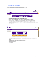
indicates whether or not LACP is used, i.e. Static Mode set to Disable means LACP is used. • Press Add. 1.2 • Under LAG Membership, add the ports that are to be included in the LAG (maximum of eight). • Expand the ports in the switch by clicking on Unit 1 • Check ports 25 and 26 • Press Apply - Netgear GSM7224v1 | Configuring Link Aggregation (LAG) between two NETGEAR manag - Page 3
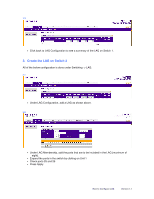
on Switch 2 All of the below configuration is done under Switching -> LAG. 2.1 • Under LAG Configuration, add a LAG as shown above. 2.2 • Under LAG Membership, add the ports that are to be included in the LAG (maximum of eight). • Expand the ports in the switch by clicking on Unit 1 • Check ports - Netgear GSM7224v1 | Configuring Link Aggregation (LAG) between two NETGEAR manag - Page 4
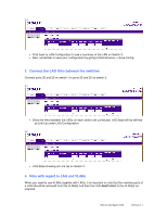
on switch 1 to ports 25 and 26 on switch 2. 3.1 • Once the links between the LAGs on each switch are connected, LAG State will be defined as Link Up under LAG Configuration. 3.2 • LAG State showing as Link Up on Switch 2. 4. Note with regard to LAG and VLANs When you need to use VLANs together with
-
 1
1 -
 2
2 -
 3
3 -
 4
4
 |
 |
How to Configure LAG
Version 1.1
How to Configure LAG
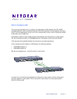
This document describes how to configure Link Aggregation (LAG) between two NETGEAR
managed switches. LAG is sometimes referred to as a port channel or a trunk (please note that a
trunk in the Link Aggregation sense is not to be confused with a trunk in terms of passing multiple
VLAN traffic over a single link).
LAG allows a switch to treat multiple physical links between two end-points as a single logical
link. All of the physical links in a LAG
must
operate in full-duplex mode at the same speed.
LAG improves the bandwidth between two end-points and adds redundancy.
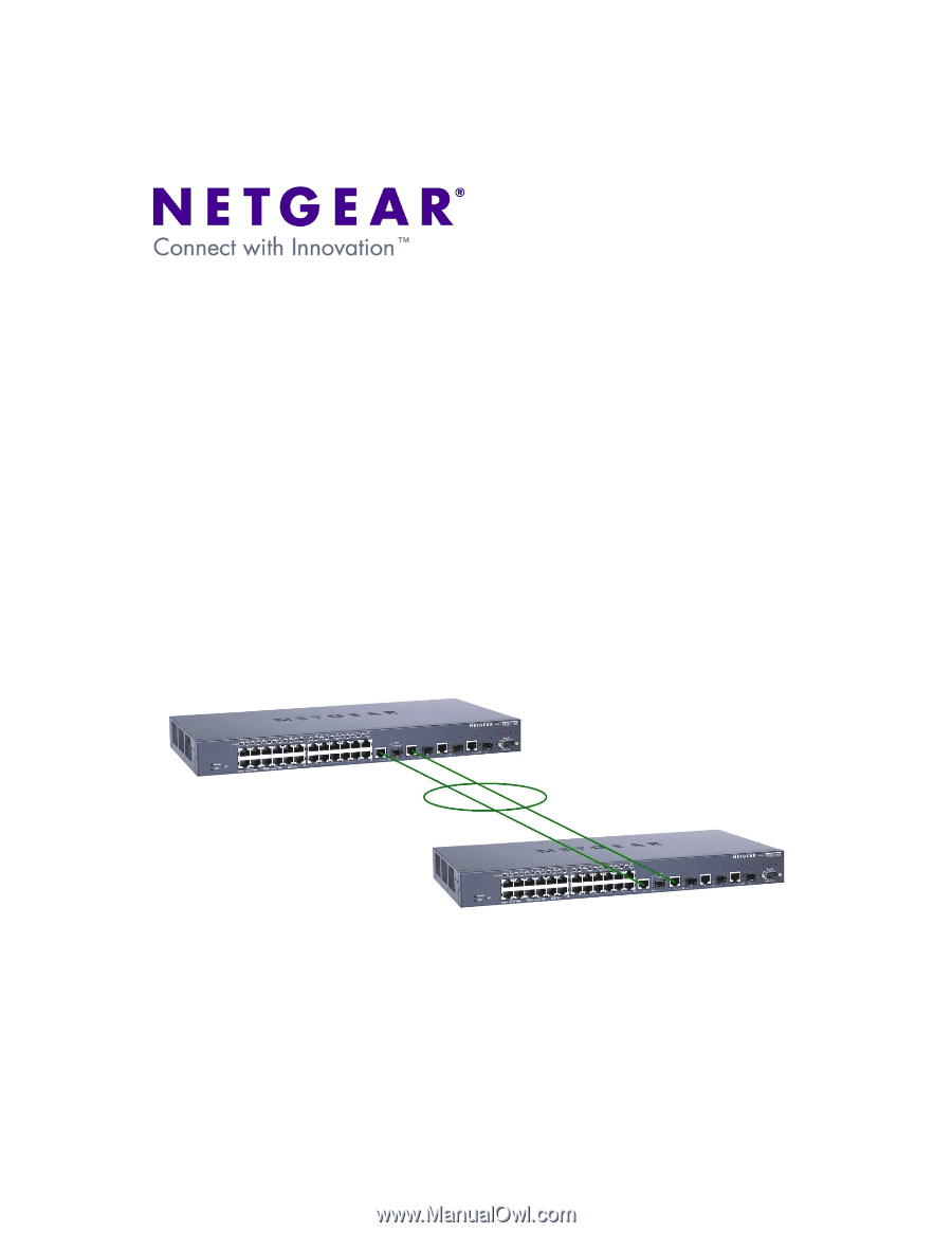
In this example we will configure a LAG between the following switches:
•
FSM7328PS (Switch 1)
•
FSM7328S (Switch 2)
We will use 2 gigabit ports - ports 25 and 26 on each switch.
It is best not to connect the links between the LAG ports on each switch until the configuration
has been applied on each switch. This is to prevent a loop (unless of course spanning tree
protocol is being used).