NordicTrack Audiorider U300 Bike Canadian English Manual - Page 8
Seat Post. Then, adjust the Seat Carriage to
 |
View all NordicTrack Audiorider U300 Bike manuals
Add to My Manuals
Save this manual to your list of manuals |
Page 8 highlights
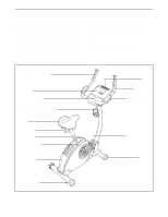
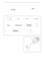
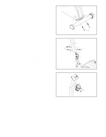
8. Slide the Bottom Handlebar Cover (33) into the slots 8 in the bottom of the Console (9). Attach the Bottom Handlebar Cover to the Handlebar (7) and the Top Handlebar Cover (30) with two M4 x 16mm Screws (54) and one M4 x 12mm Screw (64). 30 9 7 9. Turn the Seat Post Knob (20) counterclockwise sev- 9 eral turns to loosen it. Next, pull the Seat Post Knob outward, and insert the Seat Post (11) into the Frame (1). Slide the Seat Post upward or downward to the desired position, and release the Seat Post Knob. Move the Seat Post up or down slightly to make sure that the Seat Post Knob is engaged in one of the adjustment holes in the Seat Post. Then, turn the Seat Post Knob clockwise to tighten it. 10. Attach an M6 x 10mm Screw (60) to the Seat Post (11). Next, slide the Seat Carriage (19) onto the Seat Post. Then, adjust the Seat Carriage to the desired position and tighten the Seat Knob (31) into the Seat Carriage. See the inset drawing. Attach another M6 x 10mm Screw (60) to the Seat Post (11). 10 60 11 Slot 33 54 64 54 11 1 20 31 19 60 11 8
-
 1
1 -
2
-
 3
3 -
 4
4 -
 5
5 -
 6
6 -
 7
7 -
 8
8 -
 9
9 -
 10
10 -
 11
11 -
 12
12 -
 13
13 -
14
-
15
-
16
-
17
-
18
-
19
-
20
 |
 |
