NordicTrack Cx985 Elliptical English Manual - Page 6
M8 x 44mm Button Screws 84 and a Support Plate
 |
View all NordicTrack Cx985 Elliptical manuals
Add to My Manuals
Save this manual to your list of manuals |
Page 6 highlights
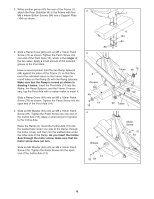
2. While another person lifts the rear of the Frame (1), attach the Rear Stabilizer (6) to the Frame with four 2 1 M8 x 44mm Button Screws (84) and a Support Plate (104) as shown. 3. Slide a Ramp Cover (48) onto an M6 x 16mm Patch Screw (76) as shown. Tighten the Patch Screw into one end of the Pivot Axle (14), which is the longer of the two axles. Apply a small amount of the included grease to the Pivot Axle. Have a second person hold the two Ramp Spacers (99) against the sides of the Frame (1) so that they cover the indicated tubes on the Frame. Align the round tubes on the Ramp (3) with the Ramp Spacers. Make sure that the Ramp is turned as shown in drawing 4 below. Insert the Pivot Axle (14) into the Ramp, the Ramp Spacers, and the Frame. If necessary, tap the Pivot Axle with a rubber mallet to insert it. Slide a Ramp Cover (48) onto an M6 x 16mm Patch Screw (76) as shown. Tighten the Patch Screw into the open end of the Pivot Axle (14). 4. Slide an M6 Washer (64) onto an M6 x 16mm Patch Screw (76). Tighten the Patch Screw into one end of the Incline Axle (13). Apply a small amount of grease to the Incline Axle. Raise the Ramp (3). Insert the Incline Axle (13) into the welded tube under one side of the Ramp, through the motor screw, and then into the welded tube under the other side of the Ramp. As you insert the Incline Axle through the motor screw, make sure that the motor screw does not turn. Slide an M6 Washer (64) onto an M6 x 16mm Patch Screw (76). Tighten the Patch Screw into the open end of the Incline Axle (13). 6 104 84 84 3 3 Grease 48 14 76 4 3 Grease Tubes 48 76 99 99 Tubes 1 Motor Screw 76 64 13 76 64 6
-
 1
1 -
 2
2 -
 3
3 -
 4
4 -
 5
5 -
 6
6 -
 7
7 -
 8
8 -
 9
9 -
 10
10 -
 11
11 -
 12
12 -
13
-
14
-
15
-
16
-
17
-
18
-
19
-
20
-
21
-
22
-
23
-
24
-
25
-
26
-
27
-
28
 |
 |
