NordicTrack Cx985 Elliptical English Manual - Page 8
Upper Handlebar Cover with an M4 x 12mm Screw
 |
View all NordicTrack Cx985 Elliptical manuals
Add to My Manuals
Save this manual to your list of manuals |
Page 8 highlights
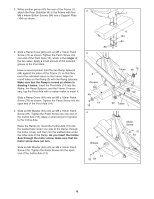
8. Locate one of the Handlebar Covers (26). Look inside of the Handlebar Cover and locate the square tabs connecting the two halves. Gently lift the tabs and disconnect the halves. Hold the two halves of the Handlebar Cover (26) around the tube on the left side of the Upright (2). Align the halves and press them together until they lock. Attach the other Handlebar Cover (26) to the right side of the Upright (2) in the same way. Hold the halves of the Upper Handlebar Cover (25) around the tube on the front of the Upright (2); be careful not to damage the Pulse Sensor Wires or the Pulse Extension Wire (not shown). Attach the Upper Handlebar Cover with an M4 x 12mm Screw (96). 9. Have another person hold the Console (17) near the Upright (2). Connect the Upper Wire Harness (115) to the wire harness on the Console (17). Connect the Pulse Extension Wire (114) to the pulse wire on the Console. Next, locate the two ground wires that are attached with a screw to the Upright (2). Connect the ground wires to the two smallest wires on the Console. Carefully insert all excess wiring up into the Console (17) and down into the Upright (2). Attach the Console to the Upright with four M4 x 16mm Screws (98). (Note: The Screws may be shipped in the console box.) Be careful to avoid pinching the wires. 10.Plug the Power Cord (116) into the Power Socket (117) at the rear of the elliptical exerciser. 8 25 96 2 26 26 26 9 17 Do not pinch the wires during this step. 114 115 Ground Wires 98 2 10 117 116 11. Make sure that all parts of the elliptical exerciser are properly tightened. Cover the floor beneath the elliptical exerciser to protect the floor from damage. Note: Some extra hardware may be left over. The elliptical exerciser is now fully assembled. If you have purchased the optional chest pulse sensor (see page 21), refer to page 9 of this manual. 8
-
 1
1 -
2
-
 3
3 -
 4
4 -
 5
5 -
 6
6 -
 7
7 -
 8
8 -
 9
9 -
 10
10 -
 11
11 -
 12
12 -
 13
13 -
14
-
15
-
16
-
17
-
18
-
19
-
20
-
21
-
22
-
23
-
24
-
25
-
26
-
27
-
28
 |
 |
