NordicTrack Cx985 Elliptical English Manual - Page 7
Pulse Sensor Wire 20 or the Pulse Extension Wire
 |
View all NordicTrack Cx985 Elliptical manuals
Add to My Manuals
Save this manual to your list of manuals |
Page 7 highlights
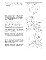
5. Identify the Left Pedal (10), which is widest at the rear and has an opening on the left side. Attach the Left Pedal to the Left Pedal Leg (4) with two M8 x 58mm Button Screws (83) and two M8 Split Washers (119). Attach the Right Pedal (11) to the Right Pedal Leg (5) in the same way. Attach two Pedal Wheels (28) and a Wheel Spacer (31) to the Wheel Frame (30) with an M10 x 78mm Bolt Set (65). Make sure that the Bolt Set, Pedal Wheels, and Wheel Spacer are oriented as shown; the bushing in the Wheel Spacer (see the inset drawing) must be facing away from the Wheel Frame. Attach the other two Pedal Wheels and the other Wheel Spacer (not shown) to the Wheel Frame (not shown) on the Right Pedal Leg (5) in the same way. 6. Have another person hold the Upright (2) in the position shown. Connect the Upper Wire Harness (115) to the Lower Wire Harness (42). Insert the connectors on the Wire Harnesses up into the Upright (2). While carefully pulling the upper end of the Upper Wire Harness (115) to remove the slack from the Wire Harnesses, insert the Upright (2) into the Frame (1). Be careful to avoid pinching the Wire Harnesses. Attach the Upright with two M10 x 108mm Button Screws (70), two M10 Split Washers (73), and two Spacers (109); make sure that the curved sides of the Spacers are facing the Upright. Be careful to avoid damaging the Wire Harnesses with the Button Screws. 7. Have another person hold the Left Handlebar (24) near the Upright (2) as shown. Connect the left Pulse Sensor Wire (20) to the Pulse Extension Wire (114). Slide the upper end of the Left Handlebar (24) into the tube on the front of the Upright (2), while sliding the lower end of the Left Handlebar onto the tube on the left side of the Upright. Attach the upper end of the Left Handlebar with two M8 x 41mm Button Bolts (85) and two M8 Jam Nuts (86); be careful not to damage the Pulse Sensor Wire (20) or the Pulse Extension Wire (114) as you insert the Button Bolts. Make sure that the Jam Nuts are resting in the hexagonal holes in the Left Handlebar. Attach the lower end of the Left Handlebar with an M8 x 38mm Button Bolt (105) and an M8 Jam Nut (86). Attach the Right Handlebar (23) to the Upright (2) in the same way. 7 5 65 28 31 30 28 65 4 Bushing 31 11 Wide End 5 10 119 83 6 Pull Do not pinch the 2 wire harnesses during this step. 73 115 70 109 42 1 73 109 7 23 85 114 20 24 86 105 2 86
-
 1
1 -
 2
2 -
 3
3 -
 4
4 -
 5
5 -
 6
6 -
 7
7 -
 8
8 -
 9
9 -
 10
10 -
 11
11 -
 12
12 -
13
-
14
-
15
-
16
-
17
-
18
-
19
-
20
-
21
-
22
-
23
-
24
-
25
-
26
-
27
-
28
 |
 |
