NordicTrack Cxt 990 Uk Manual - Page 7
Apply grease to the Arm Axle 19. Insert the Arm Axle - elliptical parts
 |
View all NordicTrack Cxt 990 manuals
Add to My Manuals
Save this manual to your list of manuals |
Page 7 highlights
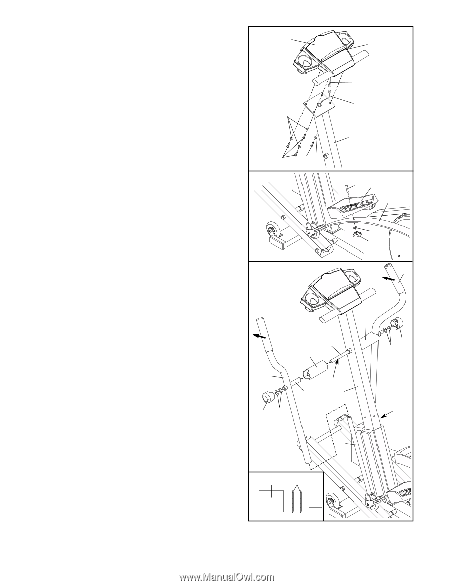
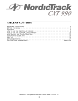
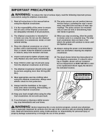
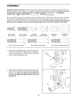
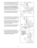
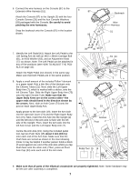
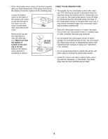
6. Connect the wire harness on the Console (87) to the Extension Wire Harness (51). 6 87 Attach the Console (87) to the Upright (2) with the four Console Screws (35) and the four Console Washers (93) packaged with the Console. Be careful to avoid pinching the wire harnesses. Snap the bookrack onto the Console (87) in the location shown. 93 Bookrack Wire Harness 51 2 7. Identify the Left Pedal (41). Attach the Left Pedal to the Left Spring Arm (3) with an M10 x 36mm Carriage Bolt (61), an M10 Washer (63), and an Adjustment Knob (77) as shown. Note: The Left Pedal can be attached in any of five positions (see HOW TO ADJUST THE PEDALS on page 10). Attach the Right Pedal (not shown) in the same way. Make sure that both Pedals are in the same position. 8. Apply a small amount of the included Teflon® lubricant to a paper towel. Rub a thin film of the lubricant onto the Chrome Tubes (21). Next, slide the Left Upper Body Arm (7), which is marked with a sticker, onto the left Chrome Tube. Slide the Right Upper Body Arm (75) onto the right Chrome Tube. Make sure that the Upper Body Arms are on the correct sides-the upper ends should bend in the direction shown by the arrows. Next, slide an Axle Cover (74) onto the post on each Upper Body Arm. Apply grease to the Arm Axle (19). Insert the Arm Axle into the right Axle Cover (74) and the Right Upper Body Arm (75). Next, insert the Arm Axle into the Upright (2) until the left end of the Arm Axle is flush with the left side of the Upright. Then, insert the Arm Axle into the left Axle Cover and the Left Upper Body Arm (7). Centre the Arm Axle (19). Using the included pedal tool, tap two Push Nuts (15) about 3 mm (1/8 in.) onto each end of the Arm Axle. Make sure that the Push Nuts are turned as shown in the inset drawing. (Note: It may be helpful if another person holds a block of wood against one end of the Arm Axle whilst you tap Push Nuts onto the other end.) Then, press an Pivot Axle Cap (34) onto each end of the Arm Axle. 35 7 35 93 8 61 41 3 63 77 75 19 74 74 34 15 7 Grease Post 2 34 15 21 21 Pedal Tool 15 19 9. Make sure that all parts of the elliptical crosstrainer are properly tightened. Note: Some hardware may be left over after assembly is completed. 7
-
 1
1 -
 2
2 -
 3
3 -
 4
4 -
 5
5 -
 6
6 -
 7
7 -
 8
8 -
 9
9 -
 10
10 -
 11
11 -
 12
12 -
13
-
14
-
15
-
16
-
17
-
18
-
19
-
20
-
21
-
22
-
23
-
24
-
25
-
26
-
27
-
28
 |
 |