Oki B8300n Guide: Installation B8300 - Page 8
B83D Installation Manual
 |
View all Oki B8300n manuals
Add to My Manuals
Save this manual to your list of manuals |
Page 8 highlights
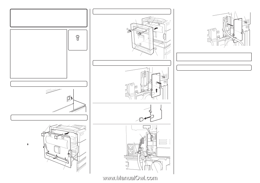
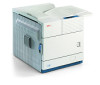
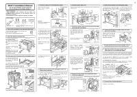
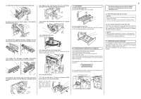
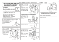
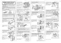
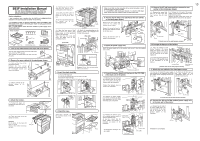
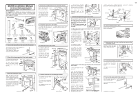
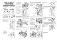
B83D Installation Manual FOR USE WITH COMPATIBLE OKI DIGITAL PRINTERS. SEE OKI DIGITAL PRINTER SERVICE MANUAL OR INSTALLATION MANUAL TO DETERMINE SUITABILITY. • Carry out the installation after checking that the DATA indicator on the operation panel is neither lit nor blinking. • For installing B83D, an optional desk (multi purpose drawer, stand/3 x 500 sheet paper drawer or stand/MPD & 2000 sheet drawer) must have been installed. • Ensure that the front mounting plates and the rear mounting plates included with the optional stand/paper drawer are securely attached. • Check that the left adjuster supplied with an optional stand/drawer has been attached. Parts included M4 Screws (M4x8) : 1 pcs. 1. Turn off the main switch of the main unit of the printer. Turn the main switch located on the front side of the main unit of the printer to the "OFF" position. Then, remove the power plug of the main unit of the printer from the outlet. "OFF" 3. Attach the duplex module to the main unit of the printer. Hang the hooks located at the upper part of the duplex module on the openings of the left door of the main unit of the printer. Hook Hook Push the lower part of the duplex module to insert the positioning bosses securely into the main unit of the printer. Tighten the two screws built in the duplex module. Positioning boss Duplex module Positioning boss 4. Connect the harness to the main unit of the printer. Remove the screw that fixes the harness cover of the main unit of the printer and then slide the harness cover up to remove it. Screw Cut out the harness cover as shown in the illustration. Harness cover Harness cover Reattach the harness cover to its original position and fix it with the removed screw. 7 Harness cover Screw Relay harness * If another peripheral device must be installed, carry out the following step at the end of the installation work. 5. Carry out the off center adjustment. Installation is now complete. 2. Remove the left side cover of the main unit of the printer. Unlock the lock release lever of the main unit of the printer and then pull out the left door. Slide the two upper covers up to remove them. Remove the lower cover by inserting a flat-blade screwdriver at three locations ( ) shown in the illustration. Then, close the left door. Top covers Left door Lower cover Lock release lever Connect the connector of the relay harness of the duplex module to the CN12 (white connector) of the PCU PWB of the main unit of the printer. Insert the snap bands to the locations shown in the illustration and fix them. Secure the earth harness using a supplied M4 screw. Cut out. CN12 Relay harness connector Snap bands PCU PWB M4 Screw Ground harness
-
 1
1 -
2
-
 3
3 -
 4
4 -
 5
5 -
 6
6 -
 7
7 -
 8
8 -
 9
9 -
 10
10 -
 11
11 -
 12
12 -
 13
13 -
14
-
15
-
16
 |
 |