Optoma PK201 User's Manual - Page 3
Roduct, Verview, Ackage, Nstalling, Attery - component cable
 |
View all Optoma PK201 manuals
Add to My Manuals
Save this manual to your list of manuals |
Page 3 highlights
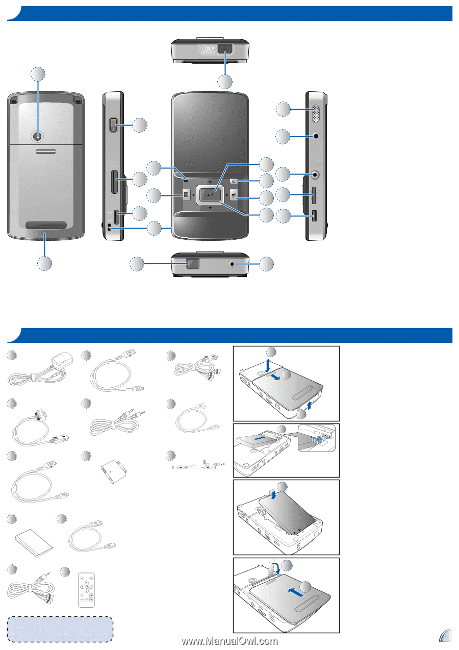
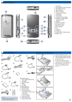
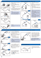
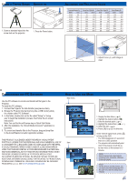
PRODUCT OVERVIEW 19 FOCUS 1 Universal I/O 4 2 5 3 6 mini HDMI 20 18 16 11 12 7 13 8 9 14 10 15 17 DC IN micro USB micro SD AV IN AUDIO OUT 1. Focus Dial 2. VGA/Component Input Connector 3. Mini HDMI Connector 4. Battery Indicator 5. Menu / Esc Button 6. Through-hole for straps 7. Enter Button 8. Power Button 9. Auto Search Source Button 10. Navigation / Volume Button (up/down/left/right) 11. Speaker 12. Audio Out Connector 13. AV Input Connector 14. MicroSD Card Slot 15. Micro USB port 16. Lens 17. DC Input 18. IR Receiver 19. Screw Hole for Tripod Convertor 20. Battery Cover PACKAGE OVERVIEW 1 8a 2 8b 3 8c INSTALLING THE BATTERY 9 1 1. Remove the battery cover. (1~3) 2. Insert the battery with the electrical contact facing downward and away 2 from the lens. (4) 3. Ensure that the battery pull tab extends from under the battery. (5) 10 4. Slide the battery cover back into 3 place over the battery pull tab. (6~7) 4 11 5 Standard Accessory 1. Power adaptor with AC Plug 4 6 2. VGA Cable 3. USB Male Cable 4. Battery 5. AV Cable Optional Accessory 6. Mini HDMI Cable 5 7 7. Remote Control 6 8. iPod Connection Kit a. USB Cable for iPod Connector 7 b. iPod Cable c. iPod Connector 9. Component Cable 10. Female USB Cable The standard accessories may vary in each region due to different applications. 11. USB to DC jack cable 3
-
 1
1 -
 2
2 -
 3
3 -
 4
4 -
 5
5 -
 6
6 -
 7
7
 |
 |