Panasonic 1100W Service Manual
Panasonic 1100W - Sharp 1 CF Microwave Manual
 |
UPC - 074000617384
View all Panasonic 1100W manuals
Add to My Manuals
Save this manual to your list of manuals |
Panasonic 1100W manual content summary:
- Panasonic 1100W | Service Manual - Page 1
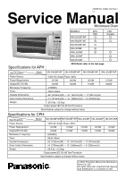
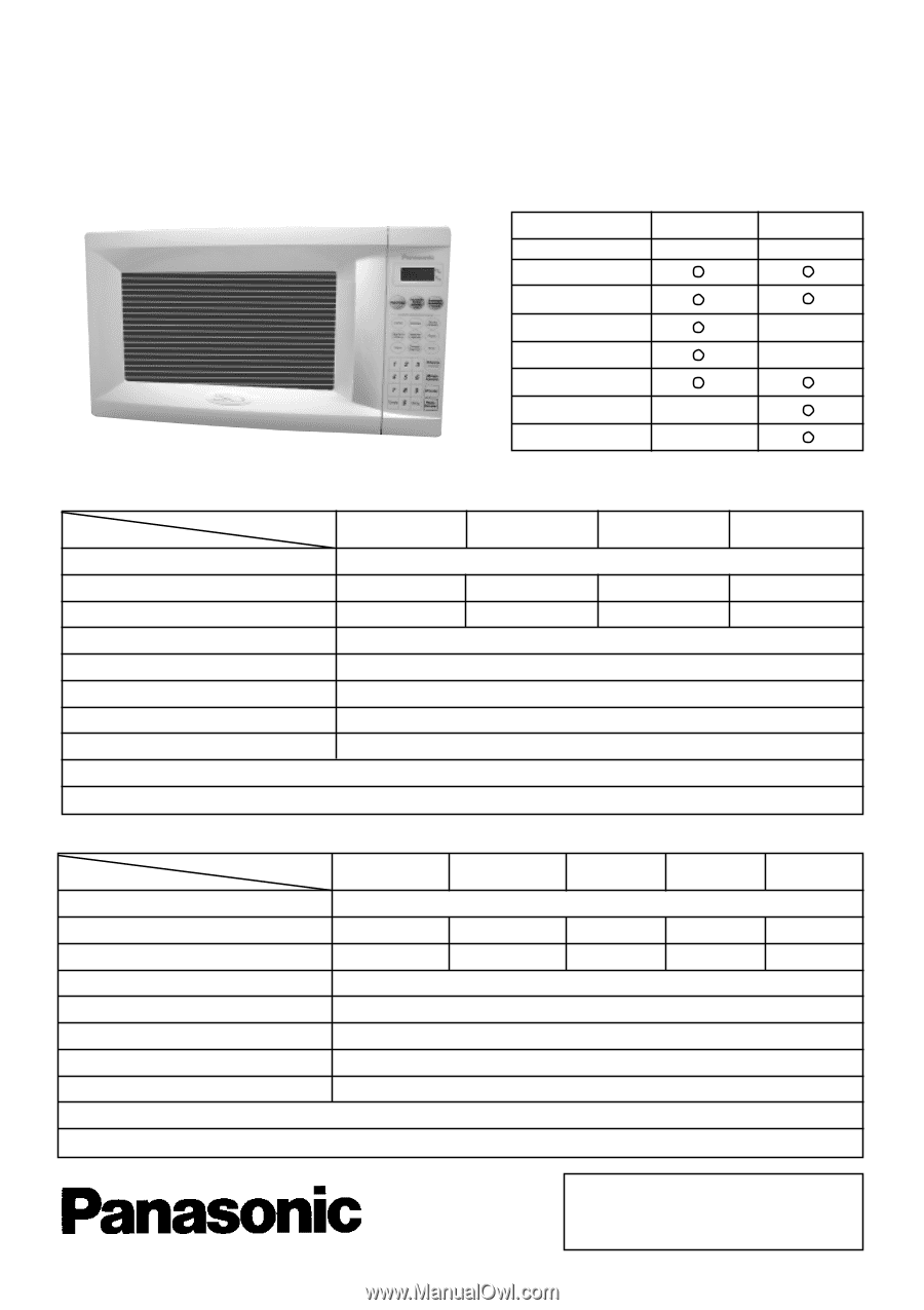
NO. SIMMC 0001002C1 E1 Service Manual Microwave Oven Specifications for APH : MODELS NN-S560BF/WF APH USA CPH Canada NN-S550BF/WF NN-S540BF/WF NN-L530BF NN-L530WF NN-L520WF NN-S510WF * RPH Model refer to the last page. Specifications: Power Source: Power Requirement: Output(IEC705-88 - Panasonic 1100W | Service Manual - Page 2
AND PARTS REPLACEMENT PROCEDURE 13 CONTROL PANEL 3 COMPONENT TEST PROCEDURE 16 OPERATION AND DIGITAL PROGRAMMER MEASUREMENTS AND ADJUSTMENTS 18 CIRCUIT TEST PROCEDURE 5 PROCEDURE FOR MEASURING MICROWAVE ENERGY LEAKAGE...19 SCHEMATIC DIAGRAMS 7 TROUBLESHOOTING GUIDE 20 DESCRIPTION - Panasonic 1100W | Service Manual - Page 3
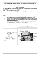
box and shipping materials. INVERTER POWER SUPPLY DIAGRAM H.V INVERTER(U) * 3 INVERTER SUPPORT BRACKET OF ORIFICE LEAD WIRE HEAT SINK (RECTIFIER BRIDGE) CHOKE COIL CURRENT TRANSFORMER SAND BAR RESISTOR HIGH VOLTAGE TRANSFORMER GROUNDING PLATE * 4 PCB DO NOT TOUCH FILM CAPACITORS VARISTOR - Panasonic 1100W | Service Manual - Page 4
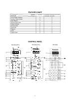
FEATURE Three Stage Cooking Inverter Turbo Defrost Auto Reheat Inverter Auto Cook Sensor Reheat Sensor Cook Quick Min Popcorn Timer Digital Clock FEATURE CHART MODEL NN-S560WF NN-S550WF NN-S540WF NN-S510WF NN-S530WF NN-S520WF NN-S560(APH) CONTROL PANEL NN-S560(CPH) NN-S550 1 1 oz 1 lb k - Panasonic 1100W | Service Manual - Page 5
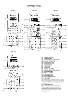
Turbo Defrost Pad (4a) Sensor Reheat Pad (4b) Auto Reheat Pad (5) Power Level Pad (6) Number Pads (7) Timer Pad (8) Clock Pad (9) Sensor Cook Pad (10) Inverter Auto Cooking Pads (11) Quick Min Pad (12) More /Less Pad (13) Cooking Guide (14) Auto Cook Pad (15) Serving/Weight Pad (16) Start Pad - Panasonic 1100W | Service Manual - Page 6
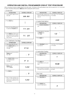
power supply cord into the wall outlet, microwave oven automatically enter into the state of lb / oz. If you want to use g / kg state, please press Start pad after pluging the power source. 1. To Set Clock OPERATION 1. Plug the power supply the oven. 2. Press Power Level pad once to set High power. - Panasonic 1100W | Service Manual - Page 7
time counts down. 2.00 3.When cooking time has elapsed, Oven beeps 5 times and shuts off. Time of day or colon Power Level P 10 (HIGH) P 9 P 8 P 7 (MED. HIGH) P 6 (MEDIUM) P 5 P 4 P 3 (MEDIUM-LOW) P 2 P 1 (LOW) Display Window P 10 P 9 P 8 P 7 P 6 P 5 P 4 P 3 P 2 P 1 10. To set Child satety Lock - Panasonic 1100W | Service Manual - Page 8
SCHEMATIC DIAGRAM (APH) SCHEMATIC DIAGRAM (APH) - 7 - - Panasonic 1100W | Service Manual - Page 9
SCHEMATIC DIAGRAM (CPH) SCHEMATIC DIAGRAM (CPH) - 8 - - Panasonic 1100W | Service Manual - Page 10
control panel and the output of the microwave oven is as shown in table. NOTE: The ON/OFF time ratio does not correspond with the percentage of microwave power since approximately 2 seconds are required for heating of magnetron filament. 2. Inverter Power Supply Circuit NEW H,V This Inverter Power - Panasonic 1100W | Service Manual - Page 11
Cooking Guide should be prepared in the microwave oven using power select and time features. Please consult variable Power Microwave Category Frozen Vegetables P1 Power HIGH Sensor Reheat (All Sensor Modeis) Category P1 Power Sensor Recheat HIGH P2 Power LOW P2 Power LOW K Factor Standard - Panasonic 1100W | Service Manual - Page 12
18 Amp fuse is blown due to the operation of short switch: make sure it is grounded properly before beginning repair work. 2. Inverter Warnings NEW H.V. DANGER OF HIGH VOLTAGE AND HIGH TEMPERATURE (HOT/LIVE) OF THE INVERTER POWER SUPPLY (U) This High Voltage Inverter Power Supply circuit supplies - Panasonic 1100W | Service Manual - Page 13
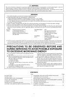
TO RADIATION FROM THE MICROWAVE GENERATOR OR OTHER PARTS CONDUCTING MICROWAVE ENERGY. IMPORTANT NOTICE NEW H.V. 1. The following components have potentials above 250V while the appliance is operating.. *h Magnetron *h High voltage transformer (Located on Inverter (U)) *h High voltage diodes (Located - Panasonic 1100W | Service Manual - Page 14
PARTS REPLACEMENT PROCEDURE 1. Magnetron (A) Discharge the high voltage capacitors, as mentioned and shown on page 11. (B) Remove 1 screw holding air guide c to magnetron. (C) Disconnect 2 high hot problems oven attaching orifice assembly. (C) Remove orifice assembly/Inverter power supply (U) from oven - Panasonic 1100W | Service Manual - Page 15
bottom hinge hole. (I) Use your left index finger to support the door's lower hinge pin while guiding the door's upper hinge pin into the top hinge hole. After replacement of the defective component parts of the door, reassemble, install, and perform microwave leakage test. 6. Turntable motor (A) - Panasonic 1100W | Service Manual - Page 16
WHILE REPLACING INVERTER POWER SUPPLY (U) 1. Make sure to leave the grounding plate in its place. 2. Make sure to securely tighten grounding screw from the bottom of chasis (base). 3. Securely connect 3 lead wire connectors. 4. Make sure the heat sink has enough space (gap) from the oven. Take - Panasonic 1100W | Service Manual - Page 17
, or wiring, always unplug the oven from its power source and discharge the high voltage capacitors. 5. Inverter Power Supply (U)for USA only DO NOT try to REPAIR this H.V. Inverter power supply (U).Replace as whole H.V. Inverter(U) Unit. DO NOT TOUCH (HOT/HIGT VOLTAGE) HEAT SINK 1. Primary - Panasonic 1100W | Service Manual - Page 18
steam sensor function of the digital programmer circuit is in working order or not, do the following test. 1) Place a water load (150 cc) in the oven. 2) Tap Sensor Reheat pad. 3) Tap Start Pad. 4) Steam Sensor detects steam about 1.5 to 4 minutes after the Start Pad is tapped. 5) T1 time cooking - Panasonic 1100W | Service Manual - Page 19
the beaker on the center of glass cook plate. Set the oven for High power and heat it for exactly one minute. (C) Stir the water again and read the temperature of the beaker. (recorded as T2). (D) The normal temperature rise at High power position for each model is as shown in table. SWITCH GAP - Panasonic 1100W | Service Manual - Page 20
the service repair spacer supplied with the oven, a leakage reading must be taken. Record this leakage reading on the repair ticket even if it is zero. A copy of this repair ticket and the microwave leakage reading should be kept by repair facility. WARNING AVOID CONTACTING ANY HIGH VOLTAGE PARTS - Panasonic 1100W | Service Manual - Page 21
or be intermittent. 3. Defective high voltage component HV Inverter Power Supply (u) Magnetron 4. Open or loose wiring of power relay B (RY-1) 5. Defective primary latch switch 6. Defective DPC or power relay B (RY-1) Refer to operation procedure. Refer to DPC troubleshooting. Adjust door and latch - Panasonic 1100W | Service Manual - Page 22
DPC mode as soon as start pad is pressed. 8. Loud buzzing noise can be heard. 9. Turntable motor does not rotate. 10. Oven stops operation during cooking. 11. Oven returns to plugged in mode after 10 seconds elapses on the Auto sensor cooking mode. 1. Loose fan and fan motor 1. Open or - Panasonic 1100W | Service Manual - Page 23
STOP! If all the above are OK up to this point, there may be a H. V. Inverter problem (SEE NOTE) NOTE: After check, unplug unit to reset to normal operation mode. NOTE: DO NOT try to repair this Inverter Power Supply (U) and also DO NOT RE-ADJUST PRESET VOLUME on the board. It is very dangerous to - Panasonic 1100W | Service Manual - Page 24
microwave oscillation at any power setting Dark or unclear display Missing or lighting of unnecessary segment H97/H98 appears in window and oven stops operation. Program High power Latch Switch 2. DPC/Power Relay ➝ Step 2 DPC Magnetron TO BE CONTINUED FOR SENSOR MODELS Auto sensor cooking does not - Panasonic 1100W | Service Manual - Page 25
21 20 EXPLODED VIEW AND PARTS LIST - 24 - 42 5 42 42 2 42 1 37 22 26 27 36 31 35 32 16 19 40 38 7 10 34 8 9 11 12 13 28 24 23 5 15 14 6 17 18 39 33 30 29 3 4 - Panasonic 1100W | Service Manual - Page 26
Part name & Description CAUTION LABEL CAUTION LABEL NAME PLATE NAME PLATE NAME PLATE NAME PLATE NAME PLATE NAME PLATE NAME PLATE NAME PLATE NAME PLATE NAME PLATE NAME PLATE NAME PLATE NAME PLATE NAME PLATE NAME PLATE BODY (U) 6 F201A4T00AP OVEN (U) 6 F201A4T10AP OVEN (U) 7 F20554T00AP COVER - Panasonic 1100W | Service Manual - Page 27
Part No. F400A4T00AP F40084T00AP F40254T00AP F41444T00AP F64505540AP Part name & Description FAN MOTOR FAN BLADE AIR GUIDE A ORIFICE EXHAUST GUIDE THERMAL CUTOUT MOUNT MICROSWITCH C H.V.INVERTER (U) MAGNETRON MAGNETRON MAGNETRON MAGNETRON 1 FUSE FUSE HOLDER GROUNDING PLATE TURNTABLE MOTOR AC CORD - Panasonic 1100W | Service Manual - Page 28
D8 D1 D4 D2 D5 D7 D6 D3 Ref.No. D1 D2 D2 D3 D4 D5 D6 D7 D7 D8 D8 Part No. B3018-1480 F30014T00BAP F30014T00HAP F302K4T00AP B30214000AP F30854T00AP Part name & Description DOOR KEY==#A DOOR A DOOR A DOOR E (U) DOOR KEY SPRING DOOR C Pcs/ set 1 1 1 1 1 1 Remarks ****BF*PH ****WF*PH F31454T00AP - Panasonic 1100W | Service Manual - Page 29
E1 E1 E2 E2 E2 E2 E2 E2 E2 E2 E2 E2 E2 E2 E3 E3 E3 E3 E4 E5 E6 Part No. F603L4T00AP F603L4T00CP F603L4T10AP F603L4T20AP F603L4T20CP F603L4T30AP F603L4T30CP F603L4T50CP F603Y4T00BAP F630Y4T00HAP F630Y4T00BCP F630Y4T00HCP F630Y4T10BAP F630Y4T10HAP F630Y4T20BAP F630Y4T20HAP F630Y4T30BAP F630Y4T30HAP - Panasonic 1100W | Service Manual - Page 30
three parts when packing. TRAY PAD OVEN WALL P3 P5 P4 FRONT VIEW 2 Put in the oven diagonaily. P6 Put in the oven 1 Part name & Description INSTRUCTION MANUAL INSTRUCTION MANUAL INSTRUCTION MANUAL INSTRUCTION MANUAL INSTRUCTION MANUAL INSTRUCTION MANUAL INSTRUCTION MANUAL INSTRUCTION MANUAL - Panasonic 1100W | Service Manual - Page 31
WIRING MATERIAL AND Ref.No. W1 W1 W2 W2 Part No. F030A4T20AP F030A4T00CP F030E4T00AP F030E4T00CP Part name & Description LEAD WIRE HARNESS LEAD WIRE HARNESS H.V. LEAD WIRE H.V. LEAD WIRE Pcs/ set 1 1 1 1 Remarks ******APH ******CPH ******APH ******CPH (S-4T0) - 30 - - Panasonic 1100W | Service Manual - Page 32
R290 R340 R10,R11 RY1 IC480 T10 ZD10 Part No. AEFB22EP20TL AECUB2F104ZK AECUB5C102KK AECUB5F103ZK ECEA1VM471B ECEA1CKA100B RESISTOR RESISTOR RESISTOR RESISTOR RESISTOR RESISTOR RESISTOR RESISTOR RESISTOR RESISTOR RESISTOR POWER RELAY SENSOR IC LOW VOLTAGE TRANSFORMER ZENER DIODE (NN-S560BFAPH - Panasonic 1100W | Service Manual - Page 33
CPH,L530BFAPH/CPH, PARTS LIST L530WFAPH/CPH,L520WFAPH/CPH,L510WFAPH/CPH) Ref.No. BZ310 Part No. AEFB22EP20TL Part name & Description BUZZER ,5% R10,R11 RD16ST751J RESISTOR 2 750Ω,1/4W,5% RY1 AEGG5G1A12 POWER RELAY 1 T10 AETP284T0AP LOW VOLTAGE TRANSFORMER 1 ZD10 AESZMTZJ5R6B - Panasonic 1100W | Service Manual - Page 34
-33- - Panasonic 1100W | Service Manual - Page 35
-34- - Panasonic 1100W | Service Manual - Page 36
/WF APH model, the different parts are listed as followings: * Any serviceman who has any quiries or order service parts, please contact own area's service company Ref.No. 2 2 2 2 E1 E2 E2 E2 E2 P1 P2 P2 P2 P2 Part No. Part name & Description Pcs/ Set Remarks F00074T20BRP NAME PLATE 1 NN-S540BF
-
 1
1 -
 2
2 -
 3
3 -
 4
4 -
 5
5 -
 6
6 -
 7
7 -
8
-
9
-
10
-
11
-
12
-
13
-
14
-
15
-
16
-
17
-
18
-
19
-
20
-
21
-
22
-
23
-
24
-
25
-
26
-
27
-
28
-
29
-
30
-
31
-
32
-
33
-
34
-
35
-
36
 |
 |
Service Manual
ORDER NO. SIMMC 0001002C1
E1
Microwave Oven
© 2000 Shanghai Matsushita Microwave
Oven Co.,Ltd
All rights reserved. Unauthorized copying
and distribution is a violation of law.
MODELS
APH
CPH
USA
Canada
®
Specifications:
Power Source:
Power Requirement:
Output(IEC705-88):
Microwave Frequency:
Timer:
Outside Dimensions:
Oven Cavity Dimensions:
Weight:
Output power:IEC705-88 Test Procedure
Specifications subject to change without notice.
Specifications for APH :
Model:
*
120V AC Single Phase, 60Hz
*
2450MHz
*
99min.99sec
*
20
”(518mm)(W)
O
±
16
”(407mm)(D)
O
±
11”(301mm)(H)
*
14
”(375mm)(W)
O
±
15
”(386mm)(D)
O
±
8
”(225mm)(H)
*
26.5 lbs. (12.0kg)
1370W
1370W
1370W
1370W
1300W
1300W
1100W
1000W
NN-S560BF/WF
NN-S550BF/WF
NN-S540BF/WF
NN-L530BF/WF
Specifications:
Power Source:
Power Requirement:
Output(IEC705-88):
Microwave Frequency:
Timer:
Outside Dimensions:
Oven Cavity Dimensions:
Weight:
Output power:IEC705-88 Test Procedure
Specifications subject to change without notice.
Specifications for CPH:
Model:
*
120V AC Single Phase, 60Hz
*
2450MHz
*
99min.99sec
*
20
”(518mm)(W)
O
±
16
”(407mm)(D)
O
±
11”(301mm)(H)
*
14
”(375mm)(W)
O
±
15
”(386mm)(D)
O
±
8
”(225mm)(H)
*
26.5 lbs. (12.0kg)
1370W
1370W
1370W
1370W
1370W
1200W
1100W
1100W
1100W
1000W
NN-S560BF/WF NN-S540BF/WF NN-L530WF
NN-L520WF
NN-S510WF
NN-S560BF/WF
NN-S550BF/WF
NN-S540BF/WF
NN-L530BF
NN-L530WF
NN-L520WF
NN-S510WF
*
RPH Model refer to the last page.