Panasonic 1100W Service Manual - Page 19
Measurements And Adjustments - amp
 |
UPC - 074000617384
View all Panasonic 1100W manuals
Add to My Manuals
Save this manual to your list of manuals |
Page 19 highlights
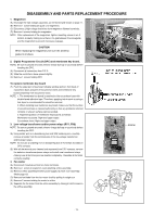
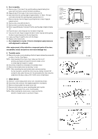
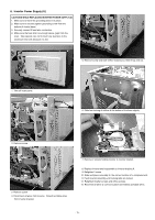
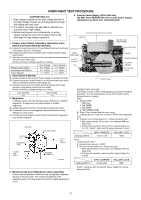
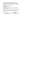
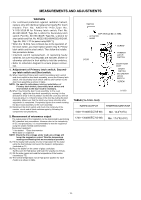
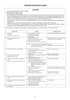
MEASUREMENTS AND ADJUSTMENTS WARNING * For continued protection against radiation hazard, replace only with identical replacement parts(For touch models Part No. ANE6142-1450,Type No. V-16G-3C26-M for Primary latch switch; Part No. A61425180AP, Type No. L-3C2-2 for Secondary latch switch; Part No. A61785180AP, Type No. L-2C2-2 for short switch and Part. No. AEG5J1EG12B/AEG5J1EG18B, Type No. G5J-1-TP for power relay B(RY1)) * When the 18 Amp. fuse is blown due to the operation of the short switch, you must replace power relay B. Primary latch switch and the short switch. Then follow the installation procedures below. * Interlock switch replacement In replacing faulty switches, be sure mounting tabs are not bent, broken or otherwise deficient in their ability to hold the switches. * Refer to schematic diagram to ensure proper connection. 1. Adjustment of Primary latch switch, Secondary latch switch and Short switch. (A) When mounting Primary latch switch,Secondary latch switch and short switch to door hook assembly, mount the Primary latch switch, the Secondary latch switch and the short switch to the door hook assembly as shown in table. NOTE: No specific adjustment during installation of Primary latch switch, Secondary latch switch and short switch to the door hook is necessary. (B) When mounting the door hook assembly to the oven assembly, adjust the door hook assembly by moving it in the direction of arrow in the illustration so that the oven door will not have any play in it. Check for play in the door by pulling the door assembly. Make sure that the latch keys move smoothly after adjustment is completed. Completely tighten the screws holding the door hook assembly to the oven assembly. (C) Reconnect the short switch and check the continuity of the monitor circuit and all latch switches again by following the components test procedures. 2. Measurement of microwave output The output power of the magnetron can be determined by performing IEC standard test procedures. However,due to the complexity of IEC test procedures, it is recommended to test the magnetron using the simple method outlined below. Necessary Equipment: *1 liter beaker *Glass thermometer *Wrist watch or stopwatch NOTE: Check the line voltage under load.Low voltage will lower the magnetron output. Take the temperature readings and heating time as accurately as possible. (A) Fill the beaker with exactly one liter of tap water.Stir the water using the thermometer and record the beaker's temperature. (recorded as T1). (B) Place the beaker on the center of glass cook plate. Set the oven for High power and heat it for exactly one minute. (C) Stir the water again and read the temperature of the beaker. (recorded as T2). (D) The normal temperature rise at High power position for each model is as shown in table. SWITCH GAP SHOULD BE
-
 1
1 -
2
-
3
-
4
-
5
-
6
-
7
-
8
-
9
-
10
-
11
-
12
-
13
-
 14
14 -
 15
15 -
 16
16 -
 17
17 -
 18
18 -
 19
19 -
 20
20 -
 21
21 -
 22
22 -
 23
23 -
 24
24 -
25
-
26
-
27
-
28
-
29
-
30
-
31
-
32
-
33
-
34
-
35
-
36
 |
 |
