Panasonic 1100W Service Manual - Page 24
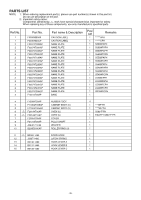
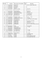
Trouble Related to Digital Programmer Circuit - parts
 |
UPC - 074000617384
View all Panasonic 1100W manuals
Add to My Manuals
Save this manual to your list of manuals |
Page 24 highlights
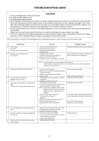
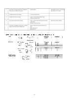
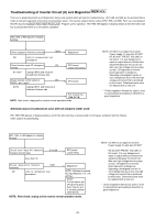
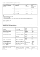
Trouble Related to Digital Programmer Circuit SYMPTOM No display when oven is first plugged in. Oven is dead. STEP 1 CHECK Fuse pattern of DPC RESULT Normal Open (NOTE) CAUSE/CORRECTIONS STEP 2 Shorted Circuit of ZNR, L.V.T., Oven Lamp etc. Replace DPC 2 Low voltage transformer (LVT) secondary voltage Abnormal 0V Normal LVT ➝ Step 3 3 IC-1 pin 8 voltage (Emitter of Q10) Abnormal Normal = 5V ZD10, Q10 ➝ Step 4 4 IC-1 pin 10 voltage (15 pin of IC-220) Abnormal Normal IC-220 ➝ IC-1, CX320 NOTE Procedure of fuse pattern repairing is as follows: 1. When the fuse pattern (PF2) opens. (1) Remove the jumper wire (PF1). (2) Insert the removed jumper wire (PF1) to "(PF2)" position and solder it. If both "PF1" and "PF2" fuse patterns are open, please replace DPC. 2. When the fuse pattern (PF4) opens. (1) Remove the jumper wire (PF3). (2) Insert the removed jumper wire (PF3) to "(PF4)" position and solder it. If both "PF3" and "PF4" fuse patterns are open, please replace DPC. NOTE:* At the time of these repairs, make visual inspection of the varistor for burning damage and examine the transformer with tester for the presence of layer shortcircuit (check primary coil resistance). If any abnormal condition is detected, replace the defective parts. SYMPTOM No key input No beep sound Power relay A(RY-2) does not turn on even though the program has been set and the start pad is tapped No microwave oscillation at any power setting Dark or unclear display Missing or lighting of unnecessary segment H97/H98 appears in window and oven stops operation. Program High power for 1 minute and conduct following test quickly, unless H97/H98 appears and oven stops. NEW H.V. STEP 1 1 1 2 1 2 1 1 CHECK Membrane switch continuity IC-1 pin 31 voltage IC-1 pin 32 voltage while operation Short circuit between pin 6 and pin 16 of IC-220 IC-1 pin 38 and pin 39 voltages while operation at high power Q220 transistor Replace display and check operation Replace IC-1 and check operation 1 Unplug CN702(2 pin) connector and measure voltage between terminals 2 Unplug CN701(3 pin) connector and measure pin 1 voltage RESULT Abnormal Normal Abnormal Normal Abnormal Normal = 5V Still not turn on RY-2 turns on Abnormal Normal 5---5V, 15---5V Abnormal Normal Normal Abnormal Normal Abnormal 0V AC line voltage of 120V 0V Approx. AC 3V CAUSE/CORRECTIONS Membrane switch IC-1 IC-1 BZ, IC-220 IC-1 ➝ Step 2 RY-2 IC-220 IC-1 ➝ Step 2 Q220 IC-220, RY-1 DISPLAY IC-1 IC-1 DISPLAY 1. Latch Switch 2. DPC/Power Relay ➝ Step 2 DPC Magnetron TO BE CONTINUED FOR SENSOR MODELS Auto sensor cooking does not operate 1 normally. (Steam Sensor cooking does not detect steam from foods.) Steam sensor terminal voltage by using high impedance tester (20k Ω/ V), when breathe on metal surface of sensor Abnormal = 0V Normal > 10~30mV Steam sensor IC-1 - 23 -
-
 1
1 -
2
-
3
-
4
-
5
-
6
-
7
-
8
-
9
-
10
-
11
-
12
-
13
-
14
-
15
-
16
-
17
-
18
-
 19
19 -
 20
20 -
 21
21 -
 22
22 -
 23
23 -
 24
24 -
 25
25 -
 26
26 -
 27
27 -
 28
28 -
 29
29 -
30
-
31
-
32
-
33
-
34
-
35
-
36
 |
 |
