Panasonic AWHB605 AWHB605 User Guide - Page 5
To Pan/tilt Head Hub Cam Cont
 |
View all Panasonic AWHB605 manuals
Add to My Manuals
Save this manual to your list of manuals |
Page 5 highlights
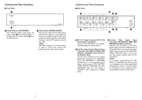
Controls and Their Functions 6 Black Burst Output [TO PAN/TILT HEAD HUB BLACK BURST OUT] (BNC Connector) This is the output jack for the reference signal generator built into the multi control hub. This signal may be used as the reference signal if the camera uses external synchronization. Connect this connector to the G/L signal input connector [G/L IN] of the pan/tilt head, or to the G/L signal input connector [TO CONTROL PANEL G/L IN] of the multi port hub using a coaxial cable (5C-2V equivalent). 7 Camera Control Output Connector [TO PAN/TILT HEAD HUB CAM CONT OUT] (BNC Connector) Connect this connector to the camera control signal input connector [CAMERA CONTROL IN] of the pan/tilt head, or to the camera control signal input connector [TO CONTROL PANEL CAMERA CONTROL IN] of the multi port hub using a coaxial cable (5C-2V equivalent). 8 Pan/Tilt Head Control Signal Input Connector [TO CONTROL PANEL PAN/TILT CONTROL IN] (RJ-45 8-pin Modular Jack) Connect this connector to the control panel pan/tilt control signal output connector [PAN/TILT CONTROL OUT] of the control panel using a 10BASE-T (UTP category 5) straight cable. 9 Preview Video Signal Output Connector [TO CONTROL PANEL PREVIEW OUT] (BNC Connector) Connect this connector to the video input connector [TO CAMERA PAN/TILT HEAD VIDEO IN] of the hybrid control panel (AW-RP501), or to the preview video input connector [PREVIEW IN] of the multi hybrid control panel (AW-RP505) using a coaxial cable (5C-2V equivalent). If the system incorporates a pan/tilt control panel (AW-RP301) or multi pan/tilt control panel (AW-RP305), the control panel is not equipped with a video input connector. If necessary, the output from the preview video signal output connector may be connected to a monitor video screen, VCR, or the like via a cable compensation device. Controls and Their Functions : Camera Control Signal Input Connector [TO CONTROL PANEL CAM CONT IN] (BNC Connector) Connect this connector to the camera control signal output connector [TO CAMERA PAN/TILT HEAD CAMERA CONTROL OUT] of the hybrid control panel (AW-RP501), or to the camera control signal output connector [TO CAMERA PAN/TILT HEAD CAMERA CONTROL OUT] of the multi hybrid control panel (AW-RP505) using a coaxial cable (5C-2V equivalent). If the system incorporates a pan/tilt control panel (AW-RP301) or multi pan/tilt control panel (AW-RP305), the control panel is not equipped with a camera control output connector. In this case, this connector should be left unconnected. ; Black Burst Output [BLACK BURST OUT] (BNC Connector) This is the output jack for the reference signal generator built into the multi control hub. This signal may be used as the reference signal for peripheral equipment that uses external synchronization. 8 9
-
 1
1 -
 2
2 -
 3
3 -
 4
4 -
 5
5 -
 6
6 -
 7
7 -
 8
8 -
 9
9 -
 10
10 -
 11
11
 |
 |
