Panasonic AWHB605 AWHB605 User Guide - Page 6
System Connections
 |
View all Panasonic AWHB605 manuals
Add to My Manuals
Save this manual to your list of manuals |
Page 6 highlights
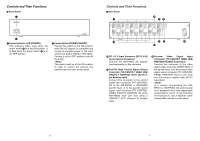
Controls and Their Functions $ Priority Switchbox < < Priority Switchbox Contacts (Terminal Panel) These are the output contacts of the priority switchbox. They should be connected to the TALLY terminals on the control panel. These terminals are not polarized. Make connections using cable conforming to the Electrical Equipment Handling Law and with a nominal cross-sectional area of 0.128 mm2 (wire number AWG26) or more. The maximum cable length (distance between priority switchbox and control panel) is 10 meters. The connection terminals differ depending on the control panel model. The correct connection terminals are listed below. AW-RP301: TALLY HOT and GND terminals. AW-RP305: Any of terminals TALLY 1 through TALLY 5 and the GND terminal. (Make sure that the pan/tilt head control connector number to which the AWHB605 is connected and the TALLY terminal number to which the priority switchbox is connected match.) Also, if the pan/tilt head is being controlled via the AW-HB605, it is necessary to select the number to which the AW-HB605 is connected using the pan/tilt head selector switch of the AWRP305. AW-RP501: TALLY HOT and GND terminals. AW-RP505: TALLY 5 and GND terminals. System Connections (Indoor Pan/tilt Head System) O Turn off the power to all pieces of equipment before making any connections. O For the control panel, use the AC adapter model AW-PS301 (sold separately), for the multi port hub and multi control hub, the AC adapter model AW-PS505 (sold separately), and for the pan/tilt head AC adapter model, the AWPS300 (sold separately). O Use an AW-PH300 series pan/tilt head and a camera from the convertible camera series. Use camera cable AW-CA50 T15 (sold separately) to make connections between the pan/tilt head and camera. O Connect the pan/tilt head (AW-PH300) to its AC adapter (AW-PS300) using a DC power cord (cable conforming to the Electrical Equipment Handling Law and with a nominal cross-sectional area of 1.25 mm2 or more, to be obtained locally). The maximum cable distance between the pan/tilt head and its AC adapter is 30 meters. O Connect the multi control hub to its AC adapter (AW-PS505). O Connect the multi port hub to its AC adapter (AW-PS505). O Connect the control panel (AW-RP301, AW-RP305, AW-RP501, AW-RP505) to its AC adapter (AW-PS301). Use a cord clamper to secure the DC cord of the AC adapter and prevent the DC plug from coming loose accidentally. O Connect the pan/tilt head and the convertible camera using the AW-CA50 T15 camera cable. O Connect the electric zoom lens iris control cable to the camera and the remote (zoom and focus control) cable to the pan/tilt head. Cord clamper DC cord Control panel AC adapter: AW-PS301 Iris control cable Remote (zoom/focus control) cable To iris connector To lens interface connector 10 11
-
 1
1 -
 2
2 -
 3
3 -
 4
4 -
 5
5 -
 6
6 -
 7
7 -
 8
8 -
 9
9 -
 10
10 -
 11
11
 |
 |
