Panasonic FV15VQL4 Installation Instructions
Panasonic FV15VQL4 Manual
 |
View all Panasonic FV15VQL4 manuals
Add to My Manuals
Save this manual to your list of manuals |
Panasonic FV15VQL4 manual content summary:
- Panasonic FV15VQL4 | Installation Instructions - Page 1
INSTRUCTIONS. Please read these instructions carefully before attempting to install, operate or service the Panasonic Ventilating Fan. Failure to comply with instructions Installation VI( In Existing Construction ) Maintenance Practical Guide to Installation Product Service 2 2 3 4 4 4-5 5 6-8 8-9 - Panasonic FV15VQL4 | Installation Instructions - Page 2
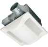
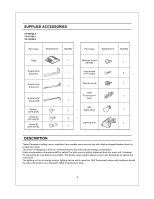
ventilation fans models use a sirocco fan with dolphin-shaped blades driven by a capacitor motor. The motor is designed to have an extended service life with reduced energy consumption. It also incorporates a thermal-cutoff for safety.The grille can be quickly detached from the main unit. A damper - Panasonic FV15VQL4 | Installation Instructions - Page 3
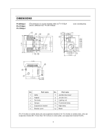
DIMENSIONS FV-08VQL4 FV-11VQL4 FV-15VQL4 (The dimension in square brackets refers to FV-15VQL4 which is different from FV-08/11VQL4) Unit: inches(mm) # C) 10 2 7/8 (73)3 1/2 (30) - 1 (25) 1 (26) 1 3/4 (45) 7 5 TIT 5 1/8 (130) [6 393 (163)] 7 7/8 (200) N CO t7 Fo W 13 4 13 (330) /11 - Panasonic FV15VQL4 | Installation Instructions - Page 4
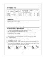
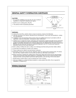
present. GENERAL SAFETY INFORMATION 1. Do not install this ventilating fan where air temperature may exceed 40°C (104°F). 2. Make certain that the electric service supply voltage is 120 V, 60 Hz. 3. Follow all local electrical and safety codes, as well as the National Electrical Code (NEC) and - Panasonic FV15VQL4 | Installation Instructions - Page 5
motor humming noise. To reduce the risk of fire or electric shock, do not use this unit with any solid-state control device. H. Before servicing or cleaning unit, switch power off at service panel and lock the service disconnecting means to prevent power from being switched on accidentally. When the - Panasonic FV15VQL4 | Installation Instructions - Page 6
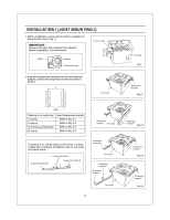
INSTALLATION I (JOIST MOUNTING-I) 1. Before installation, secure the fan body to adaptor by using thumb screw. (Fig.1) IMPORTANT : Remove the tape from damper and adaptor before installation. As show below: Thumb screw Adaptor _ _ @ Damper Remove the tape Fan body Fig.1 2. Insert the - Panasonic FV15VQL4 | Installation Instructions - Page 7
INSTALLATION I (JOIST MOUNTING-I) CONTINUED 3. Install the suspension bracket and the flange of fan body to joists by using long screws (ST4.2X20) (If spacing A between joists is 10 1/4-12 inches, install the flange of Joist fan body according to Fig.3-2, others according to Fig.3-1 install the - Panasonic FV15VQL4 | Installation Instructions - Page 8
INSTALLATION I (JOIST MOUNTING-I) CONTINUED 8. Finish ceiling work. Ceiling hole should be aligned with the edge of the flange. (Fig.6) 7 118 71 Ceiling 9. Insert the plug connector II and plug connector III into the receptacle II and receptacle III respectively, and secure the lighting unit to - Panasonic FV15VQL4 | Installation Instructions - Page 9
INSTALLATION 11 ( JOIST MOUNTING-II ) CONTINUED 4. Insert the suspension bracket into fan body (refering to step 2 of installation I, page 6) 5. Insert the fan body into joists. (Fig.9) IMPORTANT: Make sure that adaptor claws are properly inserted into body slots. 6. Secure the fan body to adaptor - Panasonic FV15VQL4 | Installation Instructions - Page 10
INSTALLATION la ( I - JOIST MOUNTING ) 4 kinds of I -joist inches (mm) C1 9/16 (14.3) C2 11/16 (17.5) c C3 31/32 (24.6) C4 1 17/32 (38.9) 0 Fan body C3 o 0 0 0 , ' C4 C1 C2 Suspension bracket III The suspension bracket III can comply with different kinds of I -joist. Thumb screw 1. - Panasonic FV15VQL4 | Installation Instructions - Page 11
INSTALLATION IV ( BETWEEN JOIST MOUNTING ) CONTINUED 3. Insert the fan body between joists. Make sure the fan body is level and square Joists (perpendicular) with the joists.(Fig.17) Ensure that distance B (7/8 inch, 21.6mm) for the thickness of ceiling board. Adaptor 0 Fan body Junction - Panasonic FV15VQL4 | Installation Instructions - Page 12
INSTALLATION V ( WOODEN HEADER ) CONTINUED 4. Follow step 5 to 11 of installation I (page 7,page 8) to complete the installation work. Adaptor Circular duct 88 a 8 6 Long screws (ST4.2X20) Conduit Junction box 0 Wire nut Lead wires Green wires Fig.21 INSTALLATION VI ( IN EXISTING - Panasonic FV15VQL4 | Installation Instructions - Page 13
MAINTENANCE I (CLEANING) WARNING: Disconnect power source before working on unit. Routine maintenance must be done every year. CAUTION: 1. Never use petrol, benzene, thinner or any other such chemicals for cleaning the ventilating fan. 2. Do not damp water to enter motor. 3. Do not soak resin - Panasonic FV15VQL4 | Installation Instructions - Page 14
II Receptacle III Fig.26 Fig.27 PRACTICAL GUIDE TO INSTALLATION Proper insulate the area around the heat that is a common problem with recessed light fixtures or some service, a nationwide system of factory service centers and AUTHORIZED INDEPENDENT SERVICE CENTERS is maintained to support - Panasonic FV15VQL4 | Installation Instructions - Page 15
PANASONIC CONSUMER ELECTRONICS COMPANY Division de Panasonic Corporation of North America, One Panasonic Way, Secaucus, NJ 07094 PANASONIC CANADA INC. 5770 Ambler Driver, Mississauga, ON L4W 2T3 www.panasonic.com X0505-5027 08VQL4420E
-
 1
1 -
 2
2 -
 3
3 -
 4
4 -
 5
5 -
 6
6 -
 7
7 -
8
-
9
-
10
-
11
-
12
-
13
-
14
-
15
 |
 |
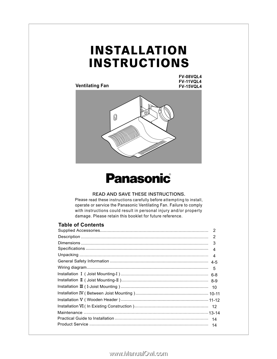
INSTALLATION
INSTRUCTIONS
Ventilating
Fan
FV-08VQL4
FV-11VQL4
FV-1
5VQL4
Panasonid
READ
AND
SAVE
THESE
INSTRUCTIONS.
Please
read
these
instructions
carefully
before
attempting
to
install,
operate
or
service
the
Panasonic
Ventilating
Fan.
Failure
to
comply
with
instructions
could
result
in
personal
injury
and/or
property
damage.
Please
retain
this
booklet
for
future
reference.
Table
of
Contents
Supplied
Accessories
2
Description
2
Dimensions
3
Specifications
4
Unpacking
4
General
Safety
Information
4-5
Wiring
diagram
5
Installation
I
(
Joist
Mounting
-I
)
6-8
Installation
II
(
Joist
Mounting
-II
)
8-9
Installation
(
I
-Joist
Mounting
)
10
Installation
IV(
Between
Joist
Mounting
)
10-11
Installation
V
(
Wooden
Header
)
11-12
Installation
VI(
In
Existing
Construction
)
12
Maintenance
13-14
Practical
Guide
to
Installation
14
Product
Service
14