Panasonic FV15VQL4 Installation Instructions - Page 10
installation
 |
View all Panasonic FV15VQL4 manuals
Add to My Manuals
Save this manual to your list of manuals |
Page 10 highlights
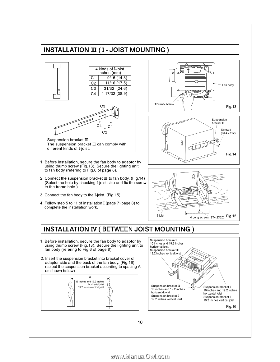
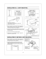
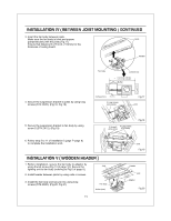
INSTALLATION la ( I - JOIST MOUNTING ) 4 kinds of I -joist inches (mm) C1 9/16 (14.3) C2 11/16 (17.5) c C3 31/32 (24.6) C4 1 17/32 (38.9) 0 Fan body C3 o 0 0 0 , ' C4 C1 C2 Suspension bracket III The suspension bracket III can comply with different kinds of I -joist. Thumb screw 1. Before installation, secure the fan body to adaptor by using thumb screw (Fig.13). Secure the lighting unit to fan body (refering to Fig.6 of page 8). 2. Connect the suspension bracket III to fan body. (Fig.14) (Select the hole by checking I-joist size and fix the screw to the frame hole.) 3. Connect the fan body to the I -joist. (Fig.15) 4. Follow step 5 to 11 of installation I (page 7-page 8) to complete the installation work. I-joist Fig.13 Suspension bracket IQ Screw II (ST4.2X12) Fig.14 4 Long screws (ST4.2X20) Fig.15 INSTALLATION IV ( BETWEEN JOIST MOUNTING ) 1. Before installation, secure the fan body to adaptor by using thumb screw (Fig.13). Secure the lighting unit to fan body (refering to Fig.6 of page 8). 2. Insert the suspension bracket into bracket cover of adaptor side and the back of the fan body. (Fig.16) (select the suspension bracket according to spacing A as shown below) A 16 inches and 19.2 inches horizontal joist 19.2 inches vertical joist IK Suspension bracket I 16 inches and 19.2 inches horizental joist Suspension bracket III 19.2 inches vertical joist Suspension bracket III 16 inches and 19.2 inches horizental joist Suspension bracket II 19.2 inches vertical joist Suspension bracket II 16 inches and 19.2 inches horizental joist Suspension bracket I 19.2 inches vertical joist Fig.16 10
-
 1
1 -
2
-
3
-
4
-
 5
5 -
 6
6 -
 7
7 -
 8
8 -
 9
9 -
 10
10 -
 11
11 -
 12
12 -
 13
13 -
 14
14 -
 15
15
 |
 |