Panasonic FV15VQL4 Installation Instructions - Page 8
<t
 |
View all Panasonic FV15VQL4 manuals
Add to My Manuals
Save this manual to your list of manuals |
Page 8 highlights
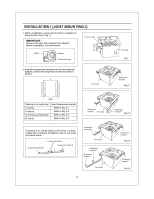
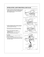
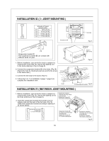
INSTALLATION I (JOIST MOUNTING-I) CONTINUED 8. Finish ceiling work. Ceiling hole should be aligned with the edge of the flange. (Fig.6) 7 118 71 Ceiling 9. Insert the plug connector II and plug connector III into the receptacle II and receptacle III respectively, and secure the lighting unit to the fan unit with 2 screw III (ST4.2X16) and 1 machine screw (M4X8). (Fig.6) Plug connectorII Plug connectorIII 10. Insert the fluorescent lamps and screw the night lamp into the lighting unit.(Fig.6) Lighting unit g screw III (ST4.2X16) Machine screw Plug connector III (M4X84)
-
 1
1 -
2
-
 3
3 -
 4
4 -
 5
5 -
 6
6 -
 7
7 -
 8
8 -
 9
9 -
 10
10 -
 11
11 -
 12
12 -
 13
13 -
14
-
15
 |
 |

INSTALLATION
I
(JOIST
MOUNTING
-I)
CONTINUED
8.
Finish
ceiling
work.
Ceiling
hole
should
be
aligned
with
the
edge
of
the
fl
ange.
(Fig.6)
9.
Insert
the
plug
connector
II
and
plug
connector
III
into
the
receptacle
II
and
receptacle
III
respectively,
and
secure
the
lighting
unit
to
the
fan
unit
with
2
screw
III
(ST4.2X16)
and
1
machine
screw
(M4X8).
(Fig.6)
10.
Insert
the
fluorescent
lamps
and
screw
the
night
lamp
into
the
lighting
unit.(Fig.6)
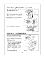
11.
Insert
mounting
springs
into
slots
as
shown
and
mount
grille
to
fan
body.(Fig.7)
11
8
7
1
7
Lighting
unit
screw
III
(ST4.2X16)
Machine
screw
(M4X8)
4
.....
imow
4<t
Ni
v
Fluorescent
lamps
4
W
Night
Lamp
inches
(mm)
Ceiling
Plug
connector
II
Plug
connectorIII
Plug
connector
III
Plug
connector
II
Receptacle
II
Receptacle
III
Fig.6
Slot
Lighting
unit
Mounting
spring
Grille
Ceiling
Fig.7
INSTALLATION
II
(JOIST
MOUNTING
-II)
1.
Disconnect
plug
connector
from
receptacle
and
remove
adaptor
from
fan
body
before
starting
installation.
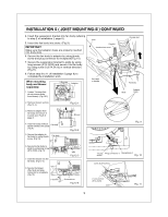
2.
Insert
the
suspension
bracket
into
the
adaptor
and
secure
it
to
joists
by
using
long
screws
(ST4.2X20).
(Fig.8)
Keep
the
distance
B
(7/8
inch,
21.6mm)
for
the
thickness
of
ceiling
board.
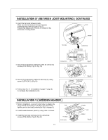
If
spacing
A
between
joists is
21
1/4
to
23
1/2
inches,
connect
suspension
bracket
II
and
III
(C4
mark
to
C4
mark)
according
to
page.
6
Select
the
suspension
bracket
according
to
spacing
A
as
shown
below.
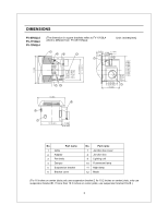
Spacing
A
between
Joists
inches
(mm)
13
1/4-15
1/2
(336-394)
16
1/2-18
3/4
(419-480)
21
1/4-23
1/2
(540-597)
suspension
bracket
suspension
bracket
I
suspension
bracket
III
suspension
bracket
II
&
III
3.
Follow
step
5
to
7
of
the
installation
I
(page
7)
to
complete
the
duct
work
and
wiring.
8
Adaptor
'N\
2
Long
screws
(ST4.2X20)
2
Long
screws
(ST4.2X20)
Joists
II
a
Adaptor
Suspension
bracket
13
1/4-15
1/2
(336-394)
16
1/2-18
3/4
(419-480)
21
1/4-231/2
(
540-597
)
inches
(mm)
to
I
I
7/8
(21.6)
Fig.8