Panasonic PT53WX42 PT47WX42F User Guide - Page 13
Program Out (prog Out), Digital Tv - Set-top Box (dtv-stb) Or Dvd Players
 |
View all Panasonic PT53WX42 manuals
Add to My Manuals
Save this manual to your list of manuals |
Page 13 highlights
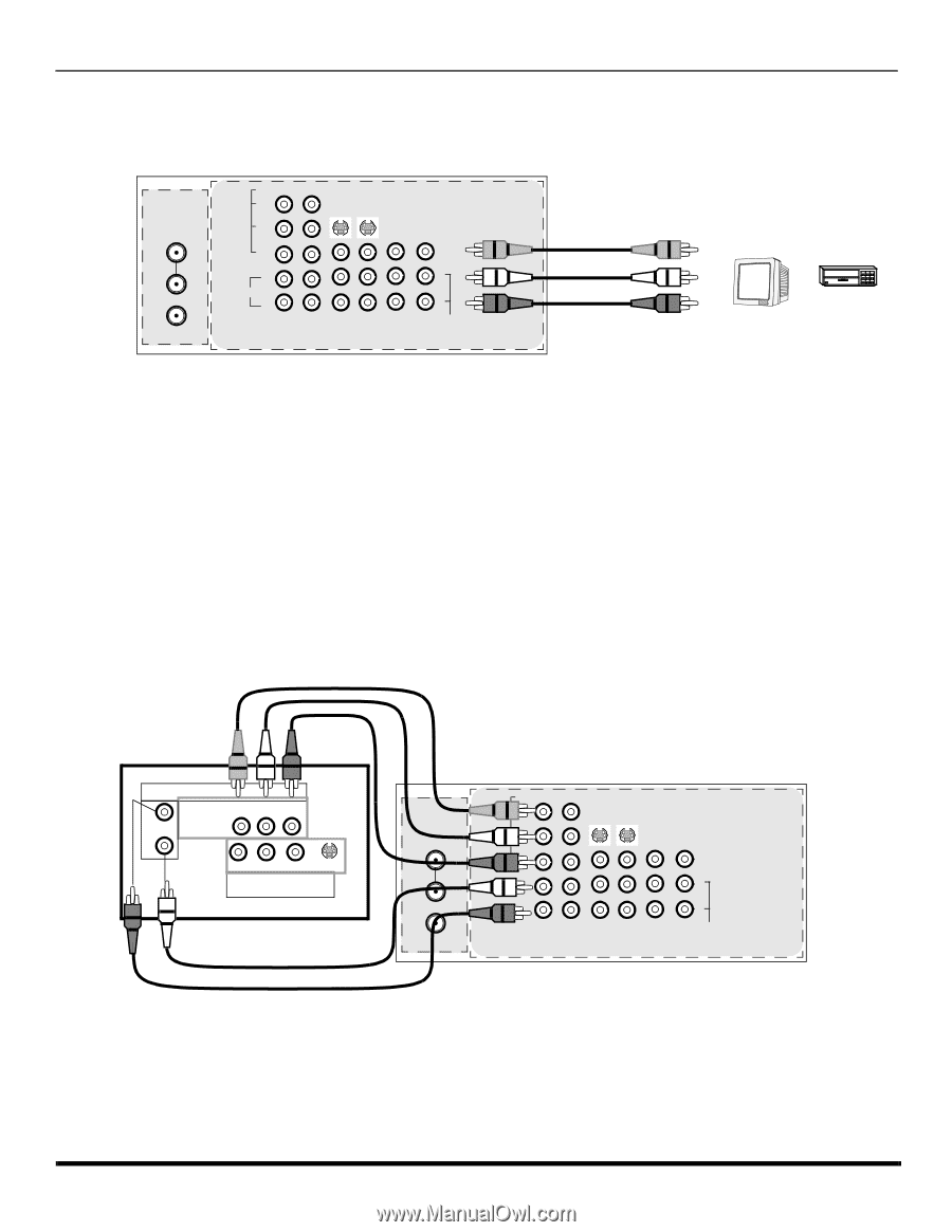
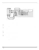
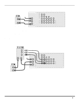
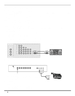
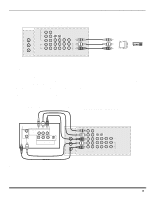
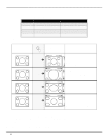
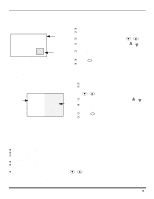
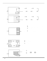
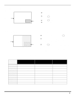
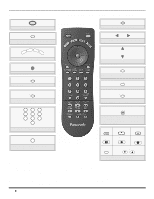
OPTIONAL EQUIPMENT CONNECTIONS Program Out Connection (PROG OUT) To use the television audio and video with optional equipment, connect the PROG OUT and TO AUDIO AMP connections on the back of the television. CONNECTIONS ON BACK OF TV ANT 1 SPLIT OUT ANT 2 VIDEO Y PB SVIDEO PR VIDEO L L AUDIO R 1 2 INPUT INPUT INPUT COMPONENT 1 2 3 VIDEO INPUTS R PROG TO OUT AUDIO AMP CABLES NOT SUPPLIED MONITOR OR VCR Procedure 1. Connect optional equipment to PROG OUT and TO AUDIO AMP terminals. 2. PROG OUT terminal display is the same as onscreen display. 3. See optional equipment manual for further instructions for recording and monitoring. Digital TV - Set-Top Box (DTV-STB) or DVD Connection This television is capable of displaying 1080i and 480p DTV signals when connected to a DTV Tuner set-top-box (STB). In order to view DTV programming, the STB must be connected to the component video inputs (Y, PB, PR) of the television. A DTV signal must be available in your area. Select the output of the STB to either 1080i or 480p. This television also utilizes a progressive scan doubler, which de-interlaces the NTSC signal and progressively scans the image. This allows you to sit close to the TV and not see the thin black horizontal lines (venetian blind effect) associated with interlaced TV pictures. Use this diagram to connect the Panasonic DTV-STB (Digital TV-Set-Top Box) or DVD Player to the back of your TV. TERMINALS ON BACK OF DTV-STB OR DVD PLAYER DTV INPUT TERMINALS ON BACK OF TV CABLES NOT SUPPLIED L-AUDIO-R DIGITAL TV OUTPUT MAIN Y PB PR VIDEO R-AUDIO-L -VIDEO S-VIDEO NTSC OUTPUT ANT 1 SPLIT OUT ANT 2 VIDEO Y PB SVIDEO PR VIDEO L L AUDIO R 1 2 INPUT INPUT INPUT COMPONENT 1 2 3 VIDEO INPUTS R PROG TO OUT AUDIO AMP Note: There are 2 sets of three video inputs, Y, PB, and PR. Separate component color inputs provide luminance and color separation. Use the L (left) and R (right) audio inputs. 11 l
-
 1
1 -
2
-
3
-
4
-
5
-
6
-
7
-
 8
8 -
 9
9 -
 10
10 -
 11
11 -
 12
12 -
 13
13 -
 14
14 -
 15
15 -
 16
16 -
 17
17 -
 18
18 -
19
-
20
-
21
-
22
-
23
-
24
-
25
-
26
-
27
-
28
-
29
-
30
-
31
-
32
-
33
-
34
-
35
-
36
-
37
-
38
-
39
-
40
-
41
-
42
-
43
-
44
-
45
-
46
-
47
-
48
-
49
-
50
-
51
-
52
-
53
-
54
-
55
-
56
-
57
-
58
-
59
-
60
-
61
-
62
-
63
-
64
-
65
-
66
-
67
-
68
-
69
-
70
-
71
-
72
-
73
-
74
-
75
-
76
-
77
-
78
-
79
-
80
-
81
-
82
-
83
-
84
-
85
-
86
-
87
-
88
-
89
-
90
-
91
-
92
-
93
-
94
-
95
-
96
-
97
-
98
-
99
-
100
-
101
-
102
-
103
-
104
-
105
-
106
-
107
-
108
-
109
-
110
-
111
-
112
 |
 |