Panasonic SC-PT464 Dvd Home Theater Sound System - Page 6
Speaker connections, Radio antenna connections, WHITE, GREEN, PURPLE
 |
UPC - 037988984220
View all Panasonic SC-PT464 manuals
Add to My Manuals
Save this manual to your list of manuals |
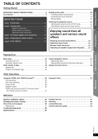
Page 6 highlights
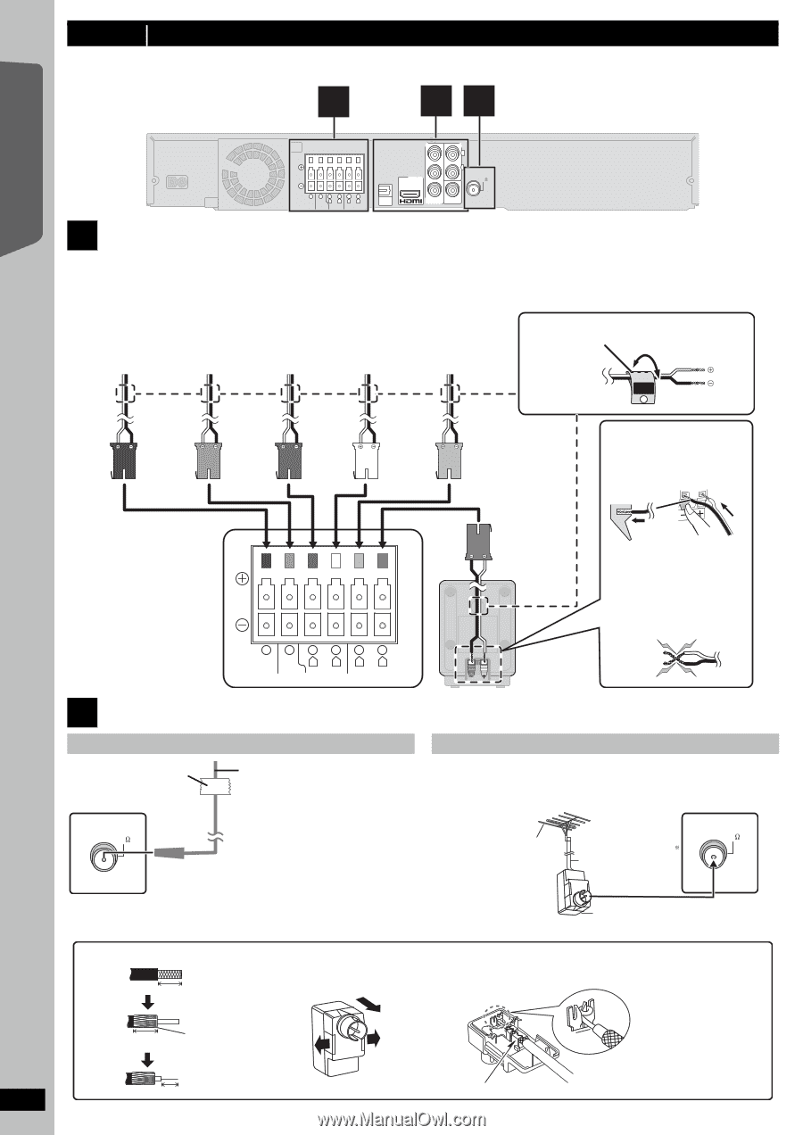
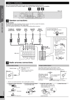
Getting Started step 2 Connections Turn off all equipment before connection and read the appropriate operating instructions. Do not connect the AC power supply cord until all other connections are complete. 1 32 6 SUBWOOFER 521 R L CENTER FRONT 43 R L SURROUND OPTICAL IN Y PB AV OUT PR AUX L R FM ANT (75 ) COMPONENT VIDEO OUT VIDEO OUT 1 Speaker connections Setup example Pay attention to the type of speaker and the connector color when you place the speakers. Connect to the terminals of the same color. Use of the speaker cable stickers is convenient when making cable connections. Main unit PURPLE GREEN SUBWOOFER CENTER RED FRONT (R) WHITE FRONT (L) GRAY SURROUND (R) e.g. Surround speaker (L) Speaker cable sticker (included) SURROUND Lch 3 Insert the wire fully, taking care not to insert beyond the wire insulation. : White : Blue Quick Start Guide Main unit 6521 R L SUBWOOFER CENTER FRONT 43 R L SURROUND BLUE SURROUND (L) Push! ● Be careful not to cross (short circuit) or reverse the polarity of the speaker wires as doing so may damage the speakers. DO NOT 2 Radio antenna connections Using an indoor antenna Using an outdoor antenna Adhesive tape Main unit FM indoor antenna (included) Affix this end of the antenna where reception is best. Use outdoor antenna if FM radio reception is poor. ≥ Disconnect the antenna when the unit is not in use. ≥ Do not use the outdoor antenna during an electrical storm. Main unit FM ANT (75 ) § Rework your outdoor antenna's 75 ≠ coaxial cable as follows. FM outdoor antenna [Using a TV antenna (not included)] The antenna should be installed by a competent technician. 75 coaxial cable (not included) FM ANT (75 ) Antenna plug (not included) 1 Remove a piece of the outer vinyl insulator. 10 mm (13/32z) 2 Carefully pull the tabs apart to remove the cover. 3 Install the coaxial cable. Clamp the cable conductor, and wind it around so that it does not contact anything else. 4 Attach the cover. RQTX0217 10 mm (13/32z) Peel back 7 mm (9/32z) 6 Clamp with pliers
-
 1
1 -
 2
2 -
 3
3 -
 4
4 -
 5
5 -
 6
6 -
 7
7 -
 8
8 -
 9
9 -
 10
10 -
 11
11 -
 12
12 -
13
-
14
-
15
-
16
-
17
-
18
-
19
-
20
-
21
-
22
-
23
-
24
-
25
-
26
-
27
-
28
-
29
-
30
-
31
-
32
-
33
-
34
-
35
-
36
 |
 |