Panasonic fv05vf2 FV05VK1 User Guide - Page 10
joists.Fig.
 |
View all Panasonic fv05vf2 manuals
Add to My Manuals
Save this manual to your list of manuals |
Page 10 highlights
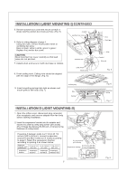
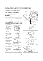
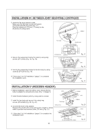
INSTALLATION IV ( BETWEEN JOIST MOUNTING ) CONTINUED 3. Insert the fan body between joists. Make sure the fan body is level and square (perpendicular)with the joists.(Fig. 17) Keep the distance B (7/8 inch, 21.6mm) for the thickness of ceiling board. Joists Adaptor Fan body Junction box 13 1/4-15 3/4 ( 336-400 ) A 16 1/2-183/4 ( 419-480 ) 3-5 ( 76-126 ) 5 4/5-74/5 ( 148-198) 4. Secure the suspension bracket to joists by using long screws (ST4.2X20) (Fig. 18, Fig. 19) 5. Secure the suspension bracket to the fan body by using screw II (ST4.2X10) (Fig. 19) 6. Follow step 5 to 9 of installation I (page 7) to complete the installation work. inches(mm) B 7/8 (21.6) 2 Long screws (ST4.2X20) Fig. 17 Joist Fig. 18 2 Screw II 4 Long screws (ST4.2X20) (ST4.2X10) Joist Fig. 19 INSTALLATION V (WOODEN HEADER) 1. Before installation, open the orifice cover. Secure the fan body to adaptor by using thumb screw. (Fig. 1 of page 5) Joist 2. Install header between joists by using nails or screws. O.? (276 3. Install the fan body and secure it by using long screws (ST4.2X20) (Fig. 20, Fig. 21) Fan body 4. Connect the duct to the adaptor. Remove the junction box cover and secure conduit or stress relief to junction box knockout hole. (7/8 inch) (Fig. 21) inches (mm) Header 143j4 (315) Joist Adaptor Fig. 20 Duct 5. Follow step 5 to 9 of installation I (page 7) to complete the installation work. 10 Joist Adaptor tt 1 A 6 Long screws (ST4.2X20) Fig. 21
-
 1
1 -
2
-
3
-
4
-
 5
5 -
 6
6 -
 7
7 -
 8
8 -
 9
9 -
 10
10 -
 11
11 -
 12
12
 |
 |
