Panasonic fv05vf2 FV05VK1 User Guide - Page 7
installation.
 |
View all Panasonic fv05vf2 manuals
Add to My Manuals
Save this manual to your list of manuals |
Page 7 highlights
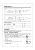
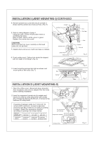
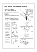
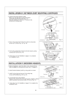
INSTALLATION I (JOIST MOUNTING-I) CONTINUED 5. Remove junction box cover and secure conduit or stress relief to junction box knock-out hole. (Fig. 5) Conduit Junction box cover 6. Refer to wiring diagram of page 4. Using wire nuts, connect house power wires to ventilating fan wires: black to black; white to white; green to green; Replace the junction box cover. CAUTION: Mount junction box cover carefully so that lead wires are not pinched. 7. Install a duct and secure it with duct tape or clamps. 8. Finish ceiling work. Ceiling hole should be aligned with the edge of the flange. (Fig. 6) Junction box Lead wires Green wires S Duct Duct tape Joist Conduit Wire nut Fig. 5 107/ (275) 9. Insert mounting springs into slots as shown and mount grille to fan body. (Fig. 7) inches (mm) Slot Ceiling Ceiling Fig. 6 Mounting spring Grille \ Fig. 7 INSTALLATION II (JOIST MOUNTING-II) 1. Open the orifice cover, disconnect plug connector from receptacle and remove adaptor from fan body before starting installation. Adaptor 2. Insert the suspension bracket into the adaptor and secure it to joists by using long screws (ST4.2X20) (Fig. 8) Keep the distance B (7/8 inch, 21.6mm) for the thickness of ceiling board. 2 Long screws (ST4.2X20) Joists If spacing A between joists is 21 1/4 to 23 1/2 inches (540 to 597mm), connect suspension bracket II and M(C4 mark to C4 mark) according to page 6. Select the suspension bracket according to spacing A as shown below. Spacing A between Joists 13 1/4-15 1/2 16 1/2-18 3/4 21 1/4-23 1/2 inches (mm) (336-394) (419-480) (540-597) suspension bracket suspension bracket I suspension suspension bracketIII bracket II&III 2 Long screws (ST4.2X20) 13 1/4-15 1/2 ( 336-394 ) Suspension bracket 16 1/2-18 3/4 ( 419-480 ) 21 1/4-23 1/2 ( 540-597 ) A inches (mm) 7/8 (21.6) 7 (1 Adaptor Fig. 8
-
 1
1 -
 2
2 -
 3
3 -
 4
4 -
 5
5 -
 6
6 -
 7
7 -
 8
8 -
 9
9 -
 10
10 -
 11
11 -
 12
12
 |
 |
